OPERATION
WARNING:
Do not use with router tables that fail to conform to safe woodworking practices and offer proper guarding for the bit. Use router tables that are UL classified and identified suitable for use with the specific router model. Failure to comply can result in an accident causing possible injury.
WARNING:
Only use router tables with proper guarding for the bit and with
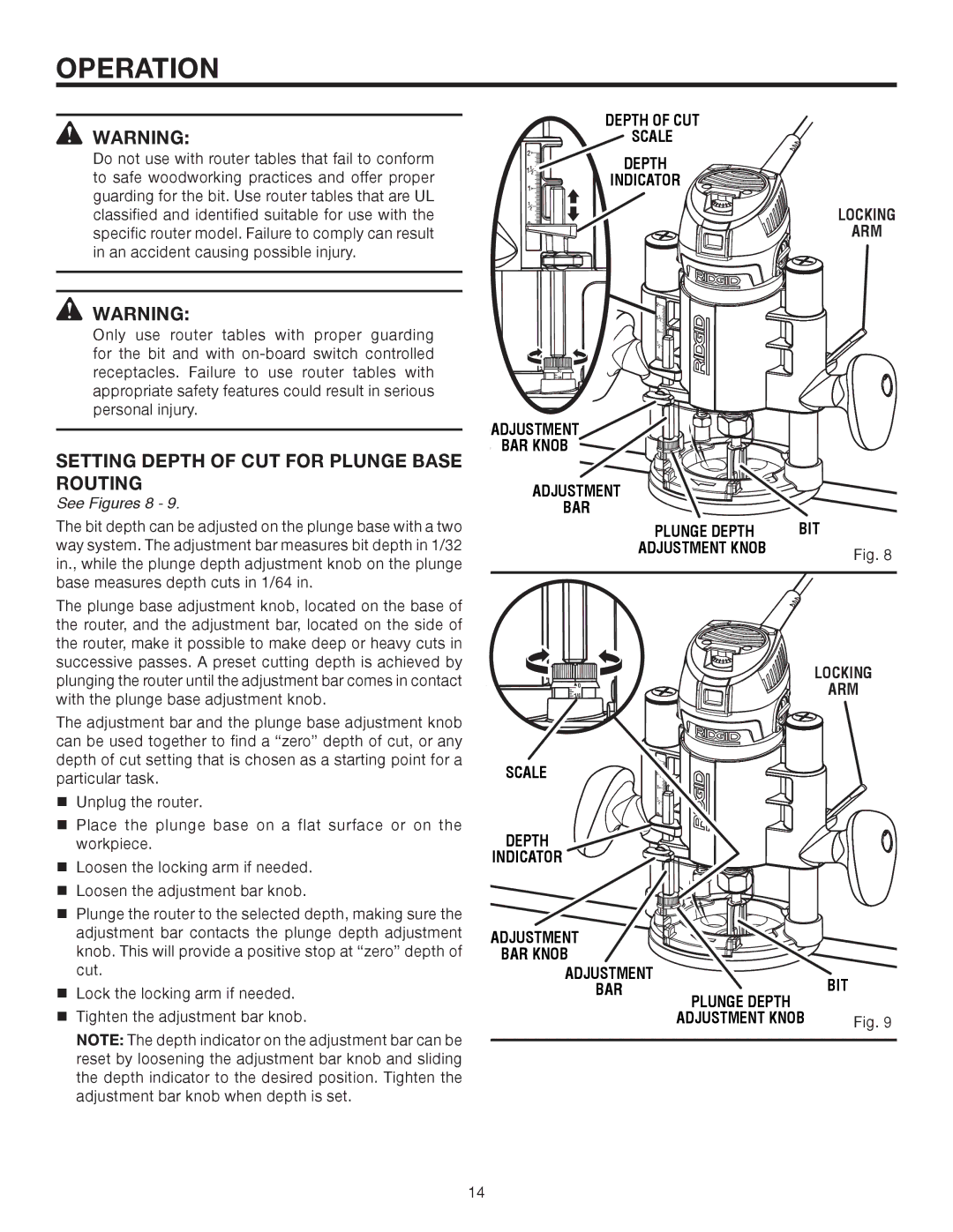
SETTING DEPTH OF CUT FOR PLUNGE BASE ROUTING
See Figures 8 - 9.
The bit depth can be adjusted on the plunge base with a two way system. The adjustment bar measures bit depth in 1/32 in., while the plunge depth adjustment knob on the plunge base measures depth cuts in 1/64 in.
The plunge base adjustment knob, located on the base of the router, and the adjustment bar, located on the side of the router, make it possible to make deep or heavy cuts in successive passes. A preset cutting depth is achieved by plunging the router until the adjustment bar comes in contact with the plunge base adjustment knob.
The adjustment bar and the plunge base adjustment knob can be used together to find a “zero” depth of cut, or any depth of cut setting that is chosen as a starting point for a particular task.
Unplug the router.
Place the plunge base on a flat surface or on the workpiece.
Loosen the locking arm if needed.
Loosen the adjustment bar knob.
Plunge the router to the selected depth, making sure the adjustment bar contacts the plunge depth adjustment knob. This will provide a positive stop at “zero” depth of cut.
Lock the locking arm if needed.
Tighten the adjustment bar knob.
NOTE: The depth indicator on the adjustment bar can be reset by loosening the adjustment bar knob and sliding the depth indicator to the desired position. Tighten the adjustment bar knob when depth is set.
| DEPTH OF CUT | |
| SCALE | |
2 | DEPTH | |
112 | ||
1 | INDICATOR | |
|
| |
1 |
| LOCKING |
2 |
| |
|
| |
0 |
| ARM |
|
| |
| 2 |
|
| 1 | |
| 1 | 2 |
| 1 |
|
| 1 |
|
| 2 | |
| 0 |
|
| 0 |
|
| 1 4 |
|
ADJUSTMENT
BAR KNOB
ADJUSTMENT
BAR
PLUNGE DEPTH | BIT |
ADJUSTMENT KNOB | Fig. 8 |
| |
|
|
1 4 |
| LOCKING |
| ARM | |
0 |
|
|
SCALE | 2 |
|
1 | ||
| 1 | 2 |
| 1 |
|
| 1 |
|
| 2 | |
| 0 |
|
DEPTH |
|
|
INDICATOR |
|
|
ADJUSTMENT
BAR KNOB
ADJUSTMENT |
| BIT |
BAR | PLUNGE DEPTH | |
|
| |
| ADJUSTMENT KNOB | Fig. 9 |
14