OPERATION
DEPTH OF CUT
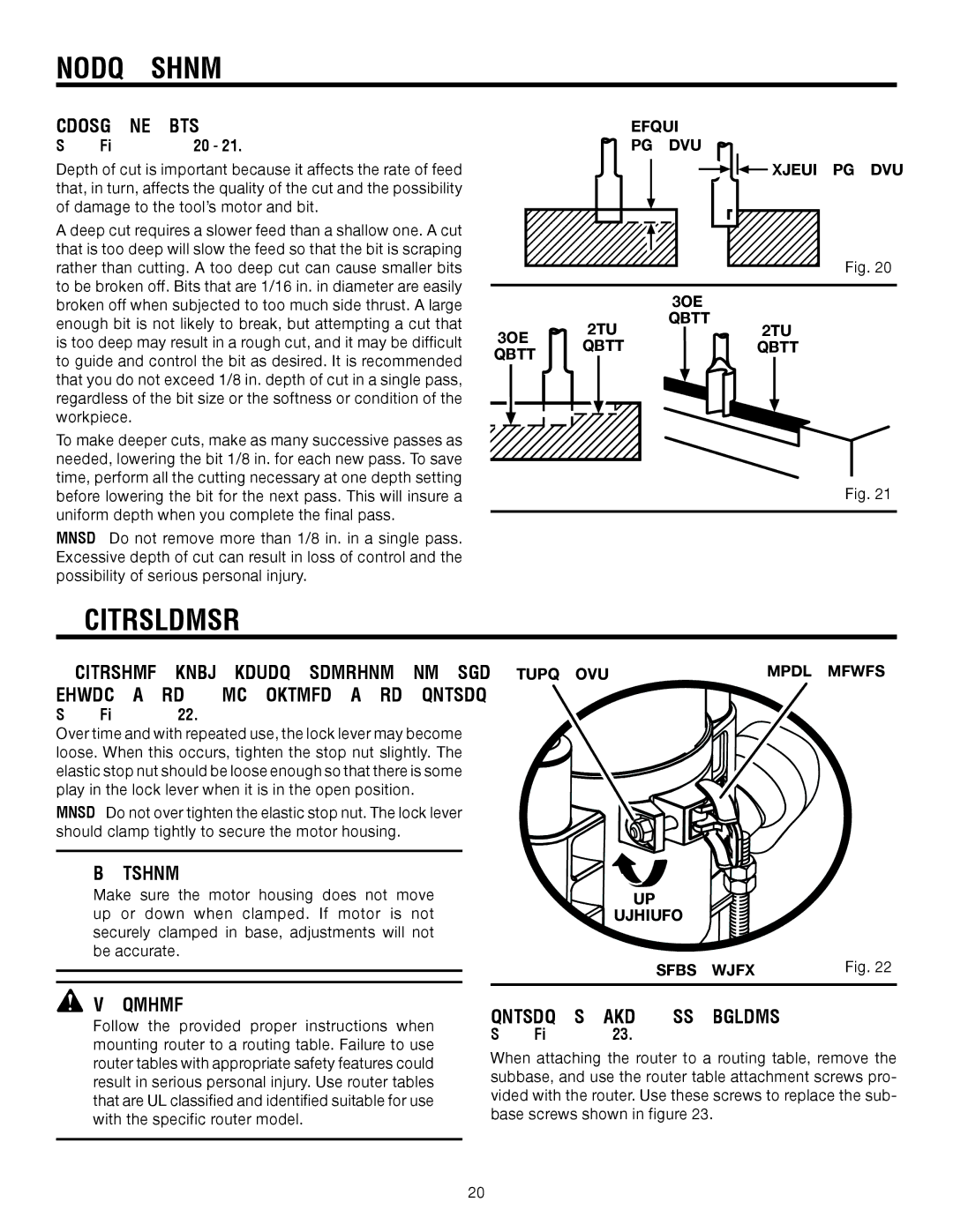
See Figures 20 - 21.
Depth of cut is important because it affects the rate of feed that, in turn, affects the quality of the cut and the possibility of damage to the tool’s motor and bit.
A deep cut requires a slower feed than a shallow one. A cut that is too deep will slow the feed so that the bit is scraping rather than cutting. A too deep cut can cause smaller bits to be broken off. Bits that are 1/16 in. in diameter are easily broken off when subjected to too much side thrust. A large enough bit is not likely to break, but attempting a cut that is too deep may result in a rough cut, and it may be difficult to guide and control the bit as desired. It is recommended that you do not exceed 1/8 in. depth of cut in a single pass, regardless of the bit size or the softness or condition of the workpiece.
To make deeper cuts, make as many successive passes as needed, lowering the bit 1/8 in. for each new pass. To save time, perform all the cutting necessary at one depth setting before lowering the bit for the next pass. This will insure a uniform depth when you complete the final pass.
NOTE: Do not remove more than 1/8 in. in a single pass. Excessive depth of cut can result in loss of control and the possibility of serious personal injury.
DEPTH
OF CUT
![]()
![]() WIDTH OF CUT
WIDTH OF CUT
Fig. 20
|
| 2ND |
|
| 1ST | PASS | 1ST |
2ND |
| ||
PASS |
| PASS | |
PASS |
| ||
|
|
|
Fig. 21
ADJUSTMENTS
ADJUSTING LOCK LEVER TENSION ON THE FIXED BASE AND PLUNGE BASE ROUTER
STOP NUT | LOCK LEVER |
See Figure 22.
Over time and with repeated use, the lock lever may become loose. When this occurs, tighten the stop nut slightly. The elastic stop nut should be loose enough so that there is some play in the lock lever when it is in the open position.
NOTE: Do not over tighten the elastic stop nut. The lock lever should clamp tightly to secure the motor housing.
CAUTION:
Make sure the motor housing does not move up or down when clamped. If motor is not securely clamped in base, adjustments will not be accurate.
TO
TIGHTEN
REAR VIEW | Fig. 22 |
![]() WARNING:
WARNING:
Follow the provided proper instructions when mounting router to a routing table. Failure to use router tables with appropriate safety features could result in serious personal injury. Use router tables that are UL classified and identified suitable for use with the specific router model.
ROUTER TABLE ATTACHMENT
See Figure 23.
When attaching the router to a routing table, remove the subbase, and use the router table attachment screws pro- vided with the router. Use these screws to replace the sub- base screws shown in figure 23.
20