OPERATION
TO CHANGE BLADE DEPTH
See Figure 21.
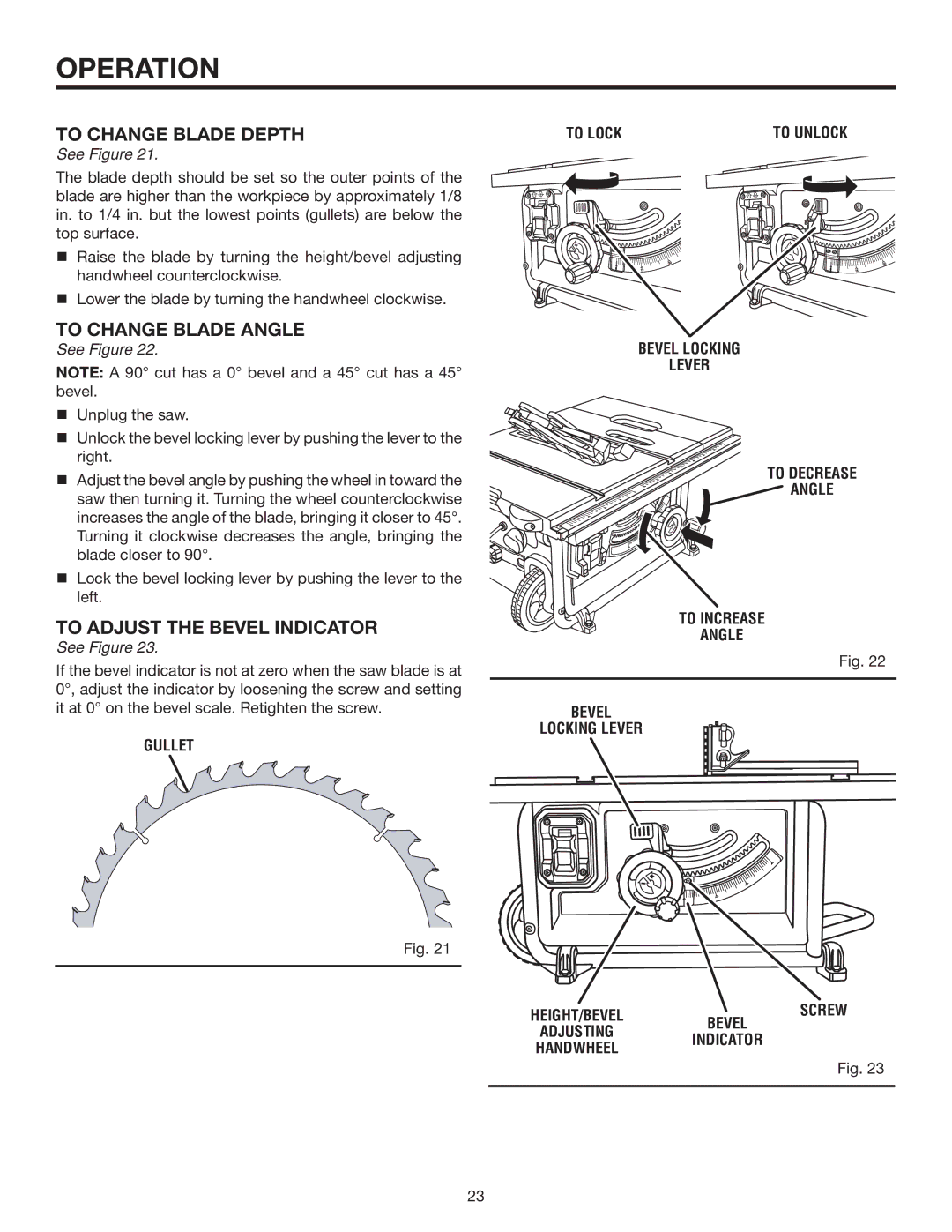
The blade depth should be set so the outer points of the blade are higher than the workpiece by approximately 1/8 in. to 1/4 in. but the lowest points (gullets) are below the top surface.
Raise the blade by turning the height/bevel adjusting handwheel counterclockwise.
Lower the blade by turning the handwheel clockwise.
TO CHANGE BLADE ANGLE
See Figure 22.
Note: A 90° cut has a 0° bevel and a 45° cut has a 45° bevel.
TO lock | TO unlock |
bevel locking
lever
Unplug the saw. |
| |
Unlock the bevel locking lever by pushing the lever to the |
| |
right. | TO DECREASE | |
Adjust the bevel angle by pushing the wheel in toward the | ||
ANGLE | ||
saw then turning it. Turning the wheel counterclockwise | ||
| ||
increases the angle of the blade, bringing it closer to 45°. |
| |
Turning it clockwise decreases the angle, bringing the |
| |
blade closer to 90°. |
| |
Lock the bevel locking lever by pushing the lever to the |
| |
left. |
| |
To Adjust the Bevel indicator | TO INCREASE | |
ANGLE | ||
See Figure 23. | ||
Fig. 22 | ||
If the bevel indicator is not at zero when the saw blade is at | ||
| ||
0°, adjust the indicator by loosening the screw and setting |
|
it at 0° on the bevel scale. Retighten the screw. | bevel |
gullet | locking lever |
|
Fig. 21
height/bevel | bevel | screw |
| ||
adjusting |
| |
indicator |
| |
handWHEEL |
| |
|
| |
|
| Fig. 23 |
|
|
|
23
