Flue Manifold Installation
•The flue manifold must exhaust to the outside. Do not exhaust into other rooms.
•The flue manifold is not designed to be positioned under floors or below the heater.
•The termination cannot be vertical.
•This appliance can only be used with one of the five types of Rinnai flue kits. The flue kits and their dimensions are listed on the previous page.
•Refer to the Flue Terminal Clearances section.
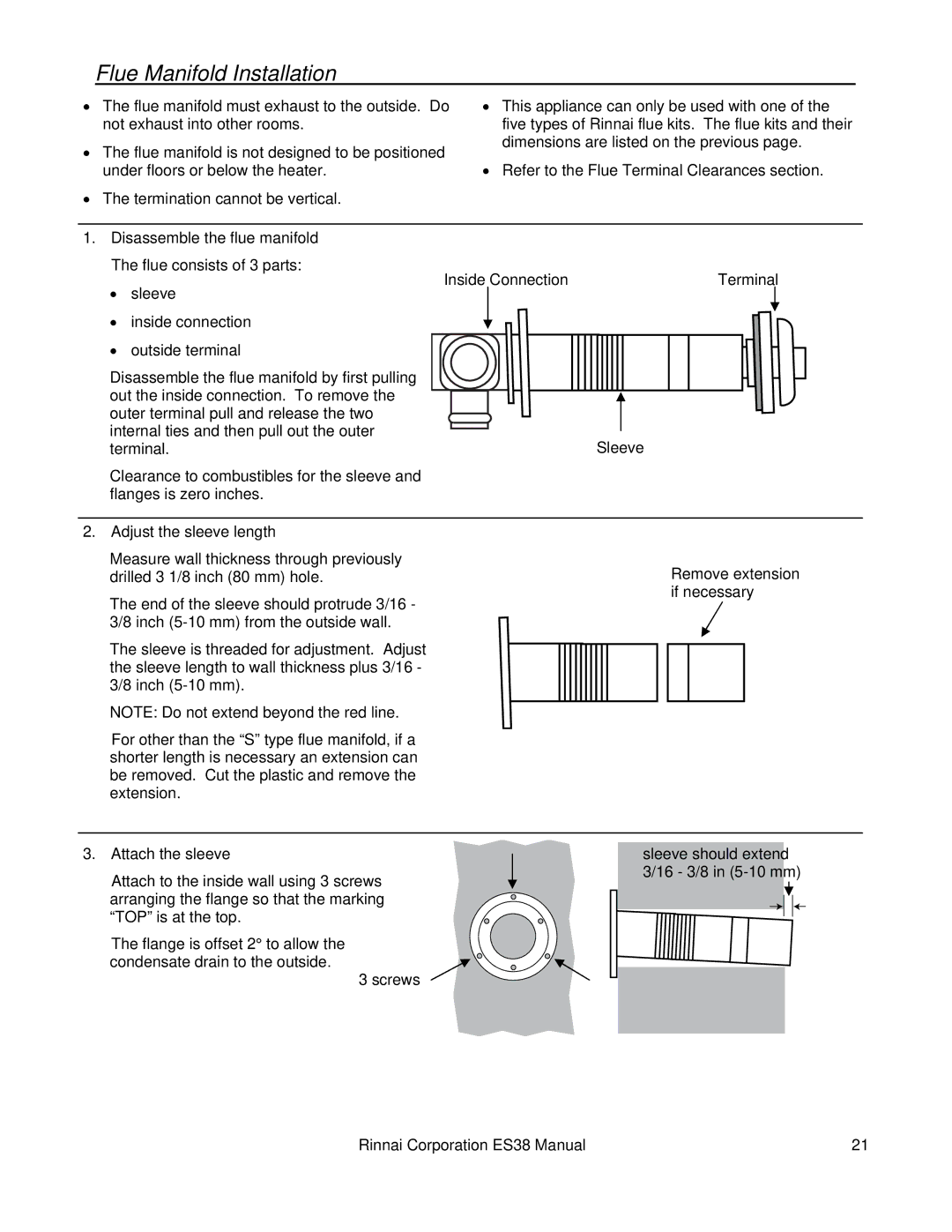
1.Disassemble the flue manifold The flue consists of 3 parts:
• | Inside Connection | Terminal |
sleeve |
|
•inside connection
•outside terminal
Disassemble the flue manifold by first pulling out the inside connection. To remove the outer terminal pull and release the two internal ties and then pull out the outer
terminal.Sleeve
Clearance to combustibles for the sleeve and flanges is zero inches.
2.Adjust the sleeve length
Measure wall thickness through previously drilled 3 1/8 inch (80 mm) hole.
The end of the sleeve should protrude 3/16 - 3/8 inch
The sleeve is threaded for adjustment. Adjust the sleeve length to wall thickness plus 3/16 - 3/8 inch
NOTE: Do not extend beyond the red line.
For other than the “S” type flue manifold, if a shorter length is necessary an extension can be removed. Cut the plastic and remove the extension.
Remove extension if necessary
3.Attach the sleeve
Attach to the inside wall using 3 screws arranging the flange so that the marking “TOP” is at the top.
The flange is offset 2° to allow the condensate drain to the outside.
3 screws
sleeve should extend 3/16 - 3/8 in
Rinnai Corporation ES38 Manual | 21 |