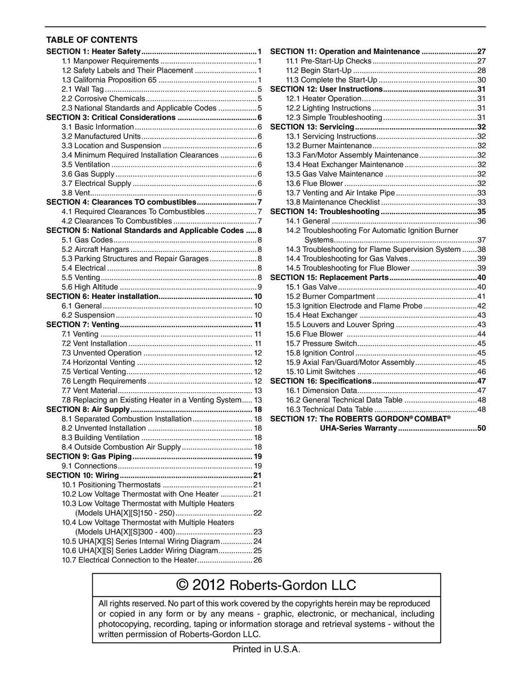
175, 225, 300, 250, 400 specifications
Roberts Gorden is a recognized leader in the field of heating solutions, particularly renowned for the development of its innovative radiant heating systems. The lineup of models including the Roberts Gorden 250, 300, 400, 150, and 225 features a blend of advanced technology, exceptional efficiency, and versatile applications that cater to various industrial and commercial needs.At the core of Roberts Gorden products is their radiant heating technology. Unlike conventional heating systems that warm the air, radiant heaters emit infrared radiation, which directly heats objects and people within a space. This method not only provides a comfortable environment but also reduces energy consumption and minimizes the loss of heat, making it an environmentally friendly choice.
The Roberts Gorden 250 model is specifically designed for smaller spaces, offering compact efficiency without sacrificing power. It features an adjustable output, allowing for tailored heating based on specific requirements. The advanced burner technology ensures optimum combustion efficiency, translating to cost savings on fuel consumption.
Moving on to the Roberts Gorden 300, this unit is well-suited for medium-sized facilities. With enhanced capabilities, the 300 model offers improved heating distribution, making it ideal for warehouses and production floors. The ease of installation and maintenance further enhances its appeal, allowing businesses to focus on their operations rather than on complicated heating systems.
The Roberts Gorden 400 is a powerhouse in the lineup, engineered for larger spaces that demand high-performance heating. Its robust construction and powerful output provide effective warmth even in challenging environments. The unit is equipped with sophisticated controls that promote energy efficiency while maintaining optimum comfort levels.
In the mid-range spectrum, the Roberts Gorden 150 and 225 models cater to businesses needing versatile heating solutions. Both models are designed with user-friendly interfaces and include safety features that comply with industry standards. Their lightweight design allows for easy installation and mobility, making them suitable for temporary or permanent heating applications.
Overall, Roberts Gorden's commitment to innovation and efficiency is evident across its product range. With a focus on sustainability and advanced heating technologies, the Roberts Gorden 250, 300, 400, 150, and 225 models provide reliable heating solutions that meet the diverse preferences of industrial and commercial users. These products are not just about warmth; they are about creating a comfortable and productive environment while minimizing energy costs and environmental impact.

