COMBAT® UHA UNIT HEATER INSTALLATION OPERATION AND SERVICE MANUAL

6.2.2Separated Combustion Heaters (Models UHAS 150 - 400)

The heaters are designed to be installed as separated combustion heaters. The vent and air intake are run as separate pipes to the wall or roof terminals. See Page 12, Figure 8. As an option, the vent and air intake are run as separate pipes to a concentric vent box and a concentric vent/air intake pipe penetrates the wall or roof.

6.3 Unvented Operation

WARNING

Carbon Monoxide Hazard

Heaters installed unvented must be interlocked with sufficient building exhaust.

Heaters must be installed according to the installation manual.

Failure to follow these instructions can result in death or injury.

For unvented operation in commercial installations, sufficient ventilation must be provided in the amount of 4 cfm per 1000 Btu/h firing rate (United States); 3 cfm per 1000 Btu/h firing rate (Canada).

WARNING: Combustion by-products contain a chemical known to the State of California to cause cancer and birth defects or other reproductive harm.

6.4 Horizontal Venting

Horizontally vented heaters must be individually vented.

Vent pipe must be sloped ¼" (.6 cm) for every 1' (.3 m). For vent lengths greater than 5' (1.5 m), condensation will form. Insulation is recommended and condensation drains may be desired. For vents pitched up toward the vent terminal, place the condensation drain within 5' (1.5 m) of the heater.

In noncombustible walls only, vent terminal (P/N 02537801-1P) may be used.

For 4'' (10 cm) vents in either combustible or noncombustible walls, use vent terminal (P/N 90502100) or equivalent insulated vent terminal. Follow the manufacturer's instructions for proper installation.

Instead of an insulated vent terminal, a listed thimble (with 2" air gap) may be used with a 4" vent cap (P/N 90502102).

6.5 Vertical Venting

Vertically vented heaters can be common vented (up to 4 heaters).

For vent lengths greater than 5' (1.5 m), condensation will form. Insulation is recommended and condensation drains may be desired. Vent from the rear of the heater cabinet then run the vent vertically and use a condensate drain at the bottom of the vertical vent.

Vent pipe must be sloped 1/4'' (.6 cm) for every 1' (.3 m).

For 4'' (10 cm), an approved vent cap (P/N 90502102) must be used.

For 6'' (15 cm) common vent, an approved vent cap (P/N 90502103) must be used.

For common vertical venting of more than two heaters, See Page 10, Figure 5.

A vent shall not extend less than 2' (.6m) above the highest point where it passes through a flat roof of a building.

6.6 Length Requirements

If using vent lengths greater than 5' (1.5 m), condensation will form in the vent pipe. Insulation and additional sealing measures (high temperature silicone at all seams) are required.

The entire vent should be insulated with foil faced fiberglass insulation (1/2" thick, 1-1/2# density minimum).

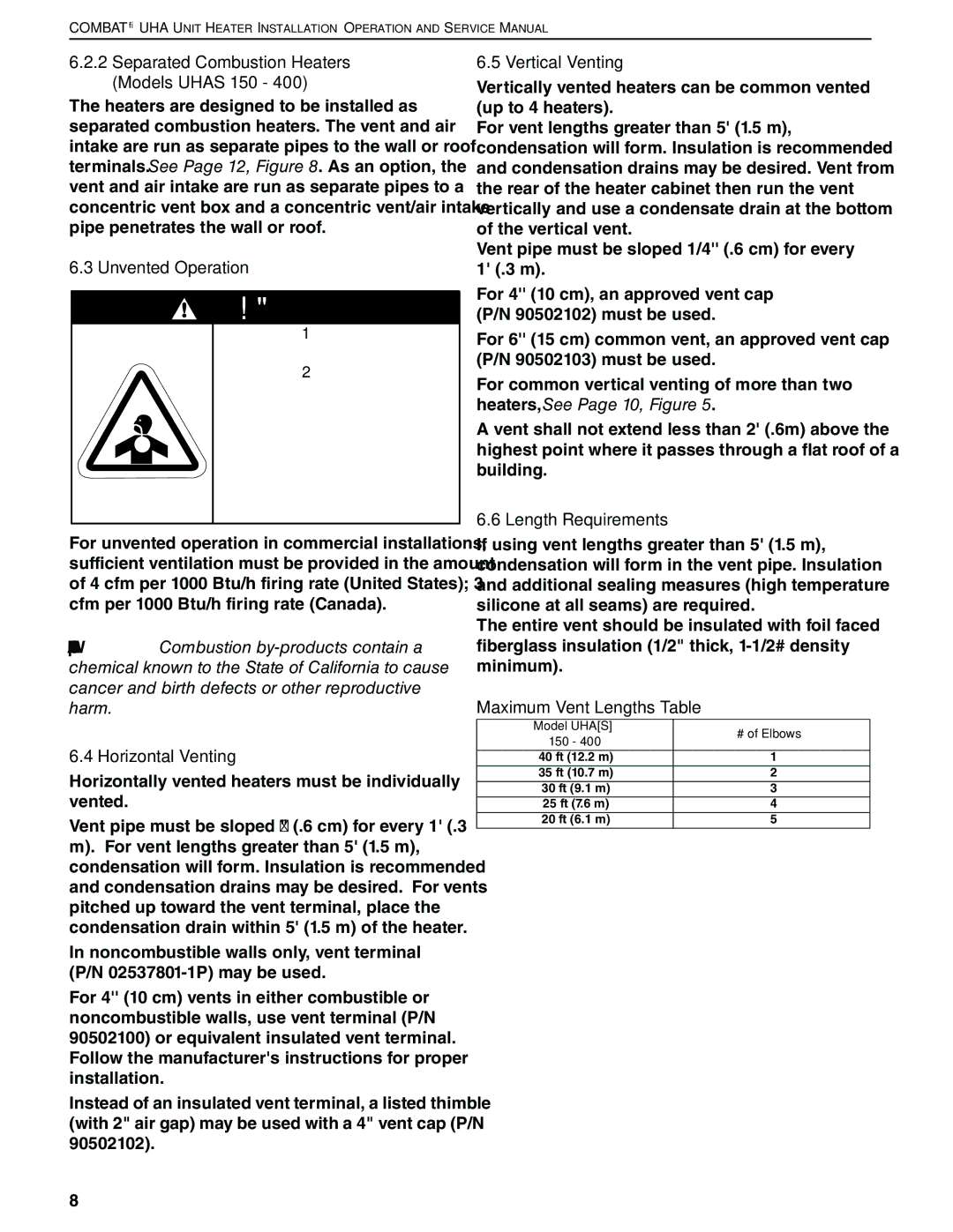
Maximum Vent Lengths Table

Model UHA[S]

# of Elbows

150 - 400


40 ft (12.2 m)

1

35 ft (10.7 m)

2

30 ft (9.1 m)

3

25 ft (7.6 m)

4

20 ft (6.1 m)

5

8

Page 14
Image 14
Roberts Gorden 200 Separated Combustion Heaters Models Uhas 150, Unvented Operation, Horizontal Venting, Vertical Venting

225 250, 175, 300, 400, 150 specifications

Roberts Gorden is a recognized leader in the field of heating solutions, particularly renowned for the development of its innovative radiant heating systems. The lineup of models including the Roberts Gorden 250, 300, 400, 150, and 225 features a blend of advanced technology, exceptional efficiency, and versatile applications that cater to various industrial and commercial needs.

At the core of Roberts Gorden products is their radiant heating technology. Unlike conventional heating systems that warm the air, radiant heaters emit infrared radiation, which directly heats objects and people within a space. This method not only provides a comfortable environment but also reduces energy consumption and minimizes the loss of heat, making it an environmentally friendly choice.

The Roberts Gorden 250 model is specifically designed for smaller spaces, offering compact efficiency without sacrificing power. It features an adjustable output, allowing for tailored heating based on specific requirements. The advanced burner technology ensures optimum combustion efficiency, translating to cost savings on fuel consumption.

Moving on to the Roberts Gorden 300, this unit is well-suited for medium-sized facilities. With enhanced capabilities, the 300 model offers improved heating distribution, making it ideal for warehouses and production floors. The ease of installation and maintenance further enhances its appeal, allowing businesses to focus on their operations rather than on complicated heating systems.

The Roberts Gorden 400 is a powerhouse in the lineup, engineered for larger spaces that demand high-performance heating. Its robust construction and powerful output provide effective warmth even in challenging environments. The unit is equipped with sophisticated controls that promote energy efficiency while maintaining optimum comfort levels.

In the mid-range spectrum, the Roberts Gorden 150 and 225 models cater to businesses needing versatile heating solutions. Both models are designed with user-friendly interfaces and include safety features that comply with industry standards. Their lightweight design allows for easy installation and mobility, making them suitable for temporary or permanent heating applications.

Overall, Roberts Gorden's commitment to innovation and efficiency is evident across its product range. With a focus on sustainability and advanced heating technologies, the Roberts Gorden 250, 300, 400, 150, and 225 models provide reliable heating solutions that meet the diverse preferences of industrial and commercial users. These products are not just about warmth; they are about creating a comfortable and productive environment while minimizing energy costs and environmental impact.