SECTION 5: MAJOR COMPONENTS
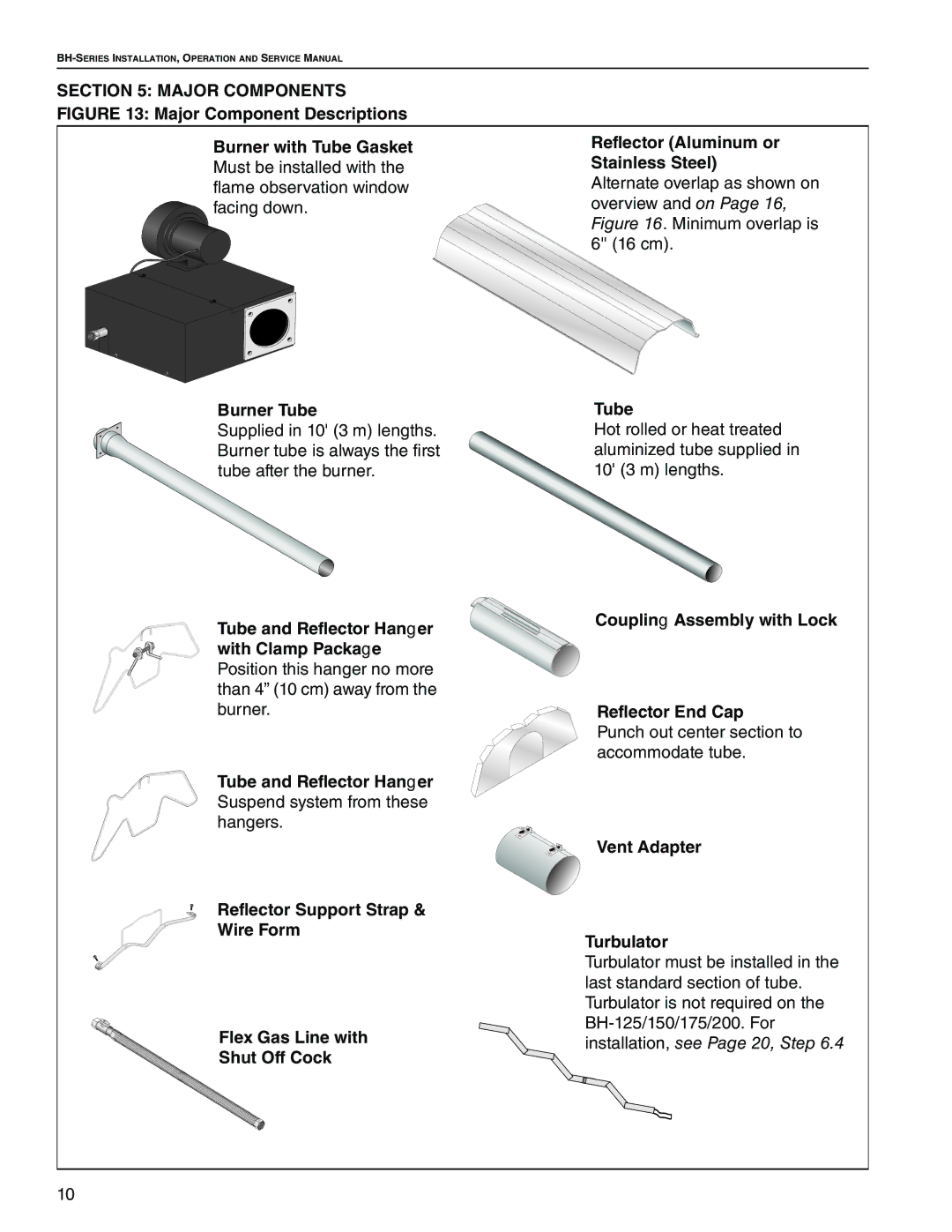
FIGURE 13: Major Component Descriptions
Burner with Tube Gasket | Reflector (Aluminum or | |
Must be installed with the | Stainless Steel) | |
flame observation window | Alternate overlap as shown on | |
facing down. | overview and on Page 16, | |
|
| Figure 16. Minimum overlap is |
|
| 6'' (16 cm). |
|
|
|
|
|
|
Burner Tube | Tube |
Supplied in 10' (3 m) lengths. | Hot rolled or heat treated |
Burner tube is always the first | aluminized tube supplied in |
tube after the burner. | 10' (3 m) lengths. |
Tube and Reflector Hanger | Coupling Assembly with Lock | |
| ||
with Clamp Package |
| |
Position this hanger no more |
| |
than 4” (10 cm) away from the |
| |
burner. | Reflector End Cap | |
| Punch out center section to | |
| accommodate tube. | |
Tube and Reflector Hanger |
| |
Suspend system from these |
| |
hangers. |
| |
| Vent Adapter | |
Reflector Support Strap & |
| |
Wire Form | Turbulator | |
| ||
| Turbulator must be installed in the | |
| last standard section of tube. | |
| Turbulator is not required on the | |
Flex Gas Line with | ||
installation, see Page 20, Step 6.4 | ||
Shut Off Cock | ||
|
10