CRV-SERIES DESIGN MANUAL

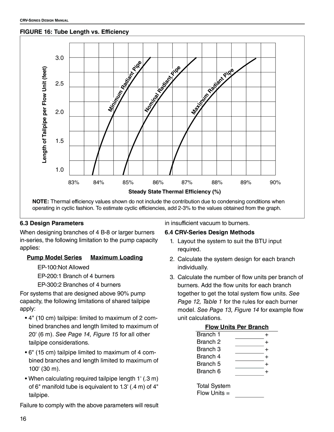
FIGURE 16: Tube Length vs. Efficiency

Length of Tailpipe per Flow Unit (feet)

3.0

2.5

2.0

1.5

1.0

M

i

n

i

m

u

m

R

a

d

i

a

n

t

P

i

p

e

o

m

i

n

a

l

R

a


a

d

i


nt


e


p


i


P


M

a

x

i

m

u

m


e


ip


P


t


n


a


i


d


a


R


83%

84%

85%

86%

87%

88%

89%

90%

Steady State Thermal Efficiency (%)

NOTE: Thermal efficiency values shown do not include the contribution due to condensing conditions when operating in cyclic fashion. To estimate cyclic efficiencies, add 2-3% to the values obtained from the graph.

6.3 Design Parameters

When designing branches of 4 B-8 or larger burners in-series, the following limitation to the pump capacity applies:

Pump Model Series Maximum Loading

EP-100:Not Allowed

EP-200:1 Branch of 4 burners

EP-300:2 Branches of 4 burners

For systems that are designed above 90% pump capacity, the following limitations of shared tailpipe apply:

4" (10 cm) tailpipe: limited to maximum of 2 com- bined branches and length limited to maximum of 20' (6 m). See Page 14, Figure 15 for all other tailpipe considerations.

6" (15 cm) tailpipe limited to maximum of 4 com- bined branches and length limited to maximum of 100' (30 m).

When calculating required tailpipe length 1' (.3 m) of 6" manifold tube is equivalent to 1.3' (.4 m) of 4" tailpipe.

Failure to comply with the above parameters will result

in insufficient vacuum to burners.

6.4CRV-Series Design Methods

1.Layout the system to suit the BTU input required.

2.Calculate the system design for each branch individually.

3.Calculate the number of flow units per branch of burners. Add the flow units for each branch together to get the total system flow units. See Page 12, Table 1 for the rules for each burner model. See Page 13, Figure 14 for example flow unit calculations.

Flow Units Per Branch

Branch 1

+

Branch 2


+

Branch 3


+


Branch 4


+


Branch 5


+


Branch 6


+


Total System


Flow Units =


16

Page 22
Image 22
Roberts Gorden CRV-B-2, CRV-B-8, CRV-B-6 Design Parameters, Pump Model Series Maximum Loading, CRV-Series Design Methods

CRV-B-4, CRV-B-2, CRV-B-6, CRV-B-8 specifications

Roberts Gorden is renowned for its innovative heating solutions, particularly the CRV series of infrared radiant heaters, which include models CRV-B-2, CRV-B-4, CRV-B-6, and CRV-B-8. These heaters are designed to provide effective and efficient heating, making them ideal for various industrial, commercial, and agricultural applications.

One of the standout features of the Roberts Gorden CRV series is its advanced infrared heating technology. Unlike conventional heating systems that heat the air, infrared heaters warm objects and people directly, allowing for a more energy-efficient and comfortable environment. This makes the CRV series particularly effective in large spaces, such as warehouses, manufacturing facilities, and greenhouses.

The CRV-B models are engineered for versatility and can be mounted in various configurations, including horizontal and vertical placements, providing installation flexibility. Each model is available in different sizes and heating outputs, ensuring that users can select a unit tailored to their specific heating requirements. The CRV-B-2, for instance, is ideal for smaller spaces, while the CRV-B-8 offers higher power for larger areas.

Moreover, these heaters come equipped with advanced control systems that allow for precise temperature regulation. The units can be integrated with building management systems, enabling users to monitor and adjust settings remotely. This feature not only enhances comfort but also contributes to energy savings, as the heaters can be programmed to operate only during necessary hours.

Structural durability is another significant characteristic of the CRV series. Constructed with high-quality materials, the heaters are designed to withstand the rigors of industrial environments while maintaining optimal performance over time. The reflective surfaces enhance heat distribution, ensuring that warmth is evenly distributed throughout the space.

Safety is paramount with Roberts Gorden’s CRV heaters. They are designed with built-in safety mechanisms, including overheat protection and automatic shut-off features to prevent accidents.

Overall, the Roberts Gorden CRV-B-2, CRV-B-4, CRV-B-6, and CRV-B-8 models exemplify cutting-edge infrared heating technology, delivering effective, efficient, and reliable heating solutions tailored to diverse applications. With a combination of flexibility, advanced control capabilities, and safety features, these heaters are an excellent choice for anyone in need of powerful heating solutions.