Wiring the
Ring and
Spade
Connectors
1. Strip back approximately 3/8" (1cm) of insulation.
![]()
![]() 3/8"
3/8" ![]()
(1cm)
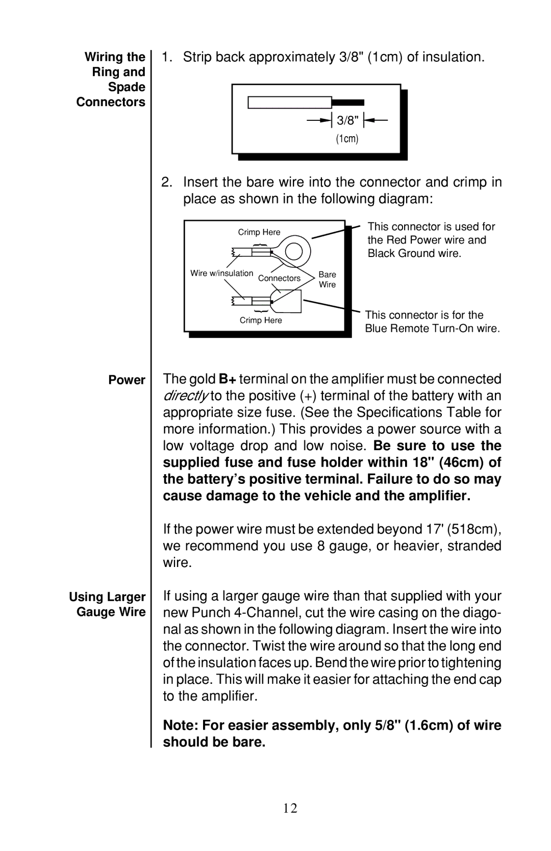
2.Insert the bare wire into the connector and crimp in place as shown in the following diagram:
Crimp Here |
| |
| { |
|
Wire w/insulation | Connectors | Bare |
|
| |
Wire
{ |
Crimp Here
This connector is used for the Red Power wire and Black Ground wire.
This connector is for the Blue Remote
Power
Using Larger Gauge Wire
The gold B+ terminal on the amplifier must be connected directly to the positive (+) terminal of the battery with an appropriate size fuse. (See the Specifications Table for more information.) This provides a power source with a low voltage drop and low noise. Be sure to use the supplied fuse and fuse holder within 18" (46cm) of the battery’s positive terminal. Failure to do so may cause damage to the vehicle and the amplifier.
If the power wire must be extended beyond 17' (518cm), we recommend you use 8 gauge, or heavier, stranded wire.
If using a larger gauge wire than that supplied with your new Punch
Note: For easier assembly, only 5/8" (1.6cm) of wire should be bare.
12