Mounting Screws
Four (4) custom, round, hex screws included in the acces- sory pack hold the unit in place. These screws are covered when the end caps are installed.
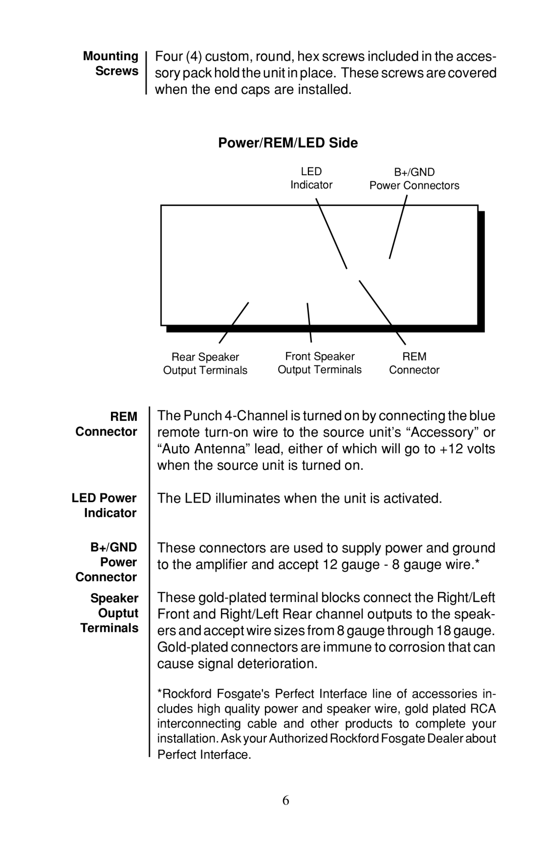
Power/REM/LED Side
LEDB+/GND
Indicator Power Connectors
REM Connector
LED Power Indicator
B+/GND
Power
Connector
Speaker
Ouptut
Terminals
Rear Speaker | Front Speaker | REM |
Output Terminals | Output Terminals | Connector |
The Punch
The LED illuminates when the unit is activated.
These connectors are used to supply power and ground to the amplifier and accept 12 gauge - 8 gauge wire.*
These
*Rockford Fosgate's Perfect Interface line of accessories in- cludes high quality power and speaker wire, gold plated RCA interconnecting cable and other products to complete your installation. Ask your Authorized Rockford Fosgate Dealer about Perfect Interface.
6