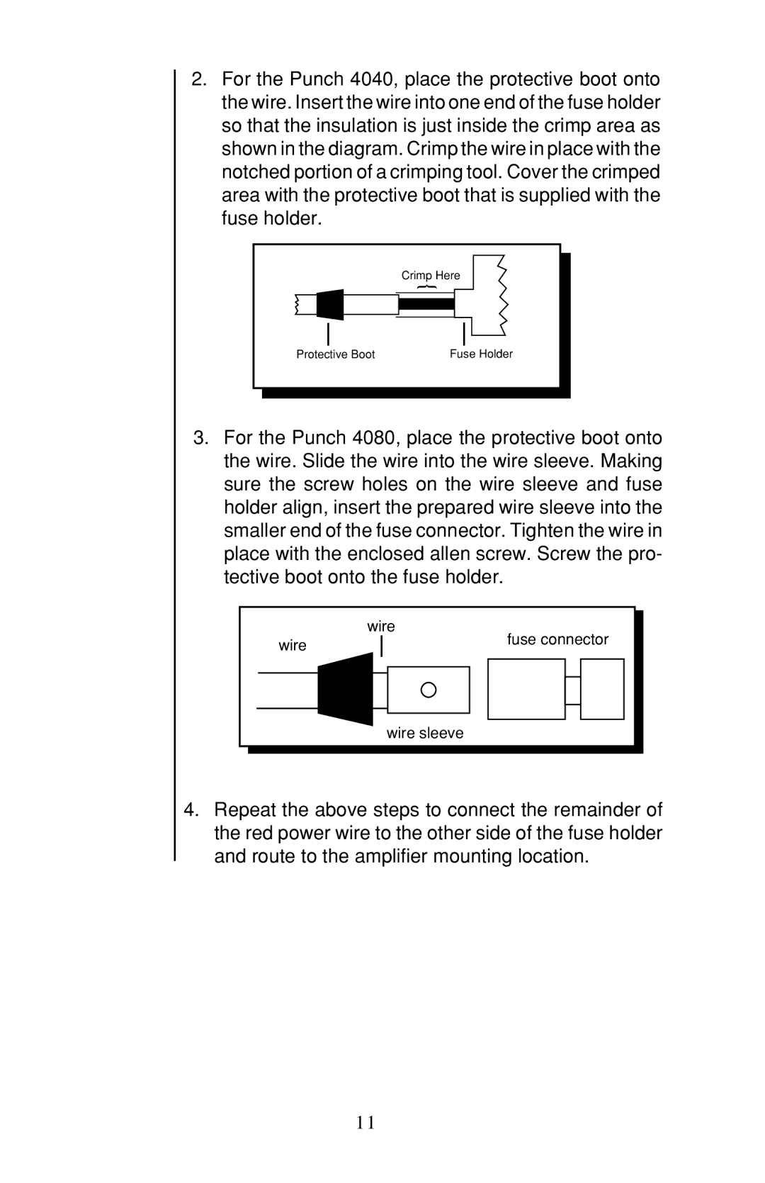
2.For the Punch 4040, place the protective boot onto the wire. Insert the wire into one end of the fuse holder so that the insulation is just inside the crimp area as shown in the diagram. Crimp the wire in place with the notched portion of a crimping tool. Cover the crimped area with the protective boot that is supplied with the fuse holder.
| Crimp Here |
| { |
Protective Boot | Fuse Holder |
3.For the Punch 4080, place the protective boot onto the wire. Slide the wire into the wire sleeve. Making sure the screw holes on the wire sleeve and fuse holder align, insert the prepared wire sleeve into the smaller end of the fuse connector. Tighten the wire in place with the enclosed allen screw. Screw the pro- tective boot onto the fuse holder.
| wire |
wire | fuse connector |
| |
| wire sleeve |
4.Repeat the above steps to connect the remainder of the red power wire to the other side of the fuse holder
and route to the amplifier mounting location.
11