To connect your IEEE-1394 CoolSNAP camera:
1.Connect either end of the CoolSNAP
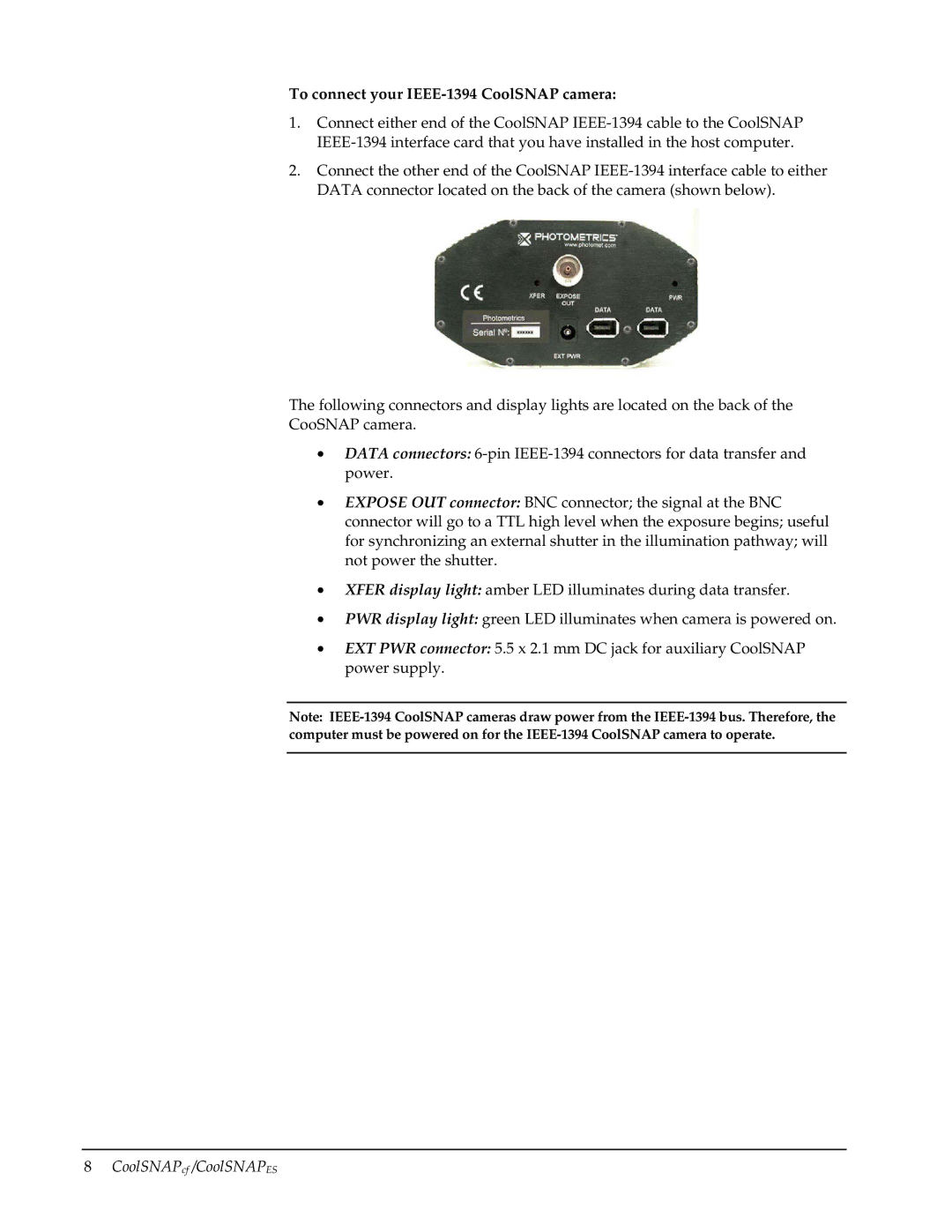
2.Connect the other end of the CoolSNAP
The following connectors and display lights are located on the back of the CooSNAP camera.
•DATA connectors:
•EXPOSE OUT connector: BNC connector; the signal at the BNC connector will go to a TTL high level when the exposure begins; useful for synchronizing an external shutter in the illumination pathway; will not power the shutter.
•XFER display light: amber LED illuminates during data transfer.
•PWR display light: green LED illuminates when camera is powered on.
•EXT PWR connector: 5.5 x 2.1 mm DC jack for auxiliary CoolSNAP power supply.
Note: