Local unit to Remote unit cabling
(PC, SUN, PC-Serial/Audio Models)
Connect up to 1,000 feet of CAT-5 “solid core” cable from the Local Units “Twisted Pair Link” RJ45 connector to the Remote Units “Twisted Pair Link” RJ45 connector. (See Figures 6, 7, or 8)
(MINI Model)
Connect up to 150 feet of CAT-5 “solid core” cable for the MINI model from the Local Units “Link” RJ45 connector to the Remote Units “Link” RJ45 connector on rear panel. (See Figure 9)
Connecting to a Rose switch
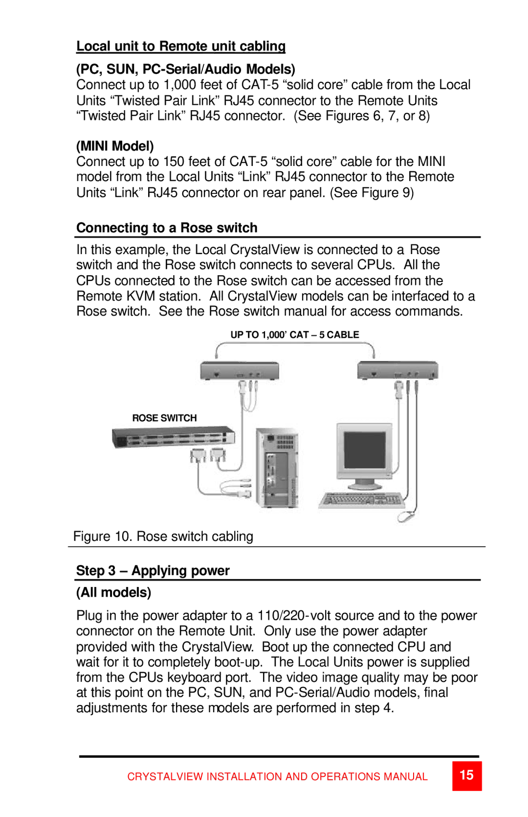
In this example, the Local CrystalView is connected to a Rose switch and the Rose switch connects to several CPUs. All the CPUs connected to the Rose switch can be accessed from the Remote KVM station. All CrystalView models can be interfaced to a Rose switch. See the Rose switch manual for access commands.
UP TO 1,000’ CAT – 5 CABLE
ROSE SWITCH
Figure 10. Rose switch cabling
Step 3 – Applying power
(All models)
Plug in the power adapter to a 110/220-volt source and to the power connector on the Remote Unit. Only use the power adapter provided with the CrystalView. Boot up the connected CPU and wait for it to completely boot-up. The Local Units power is supplied from the CPUs keyboard port. The video image quality may be poor at this point on the PC, SUN, and PC-Serial/Audio models, final adjustments for these models are performed in step 4.
CRYSTALVIEW INSTALLATION AND OPERATIONS MANUAL