3 Installing Your EM1
A.Getting Started
•Locate the desired placement of components to ensure a proper fit. Make sure the monitor has enough room for desired movement.
Warning:
Excessive moisture and condensation will damage unit. Be sure your chosen location for the interface box and monitor are in a clean dry area.
•Ensure there is a wall plug within 4’ of desired Tuner module location before mounting any components.
•The Tuner module should be mounted on a flat solid surface. Do not mount on an uneven surface. Doing so will cause damage to the unit.
B.Mounting of Components
Table Top or Under Counter Mount
•Use a 1/8” standard flat screw driver to remove the base cover using the access notch shown
below. Be careful not to scar or damage cover.
Page 4
3 Installing Your EM1
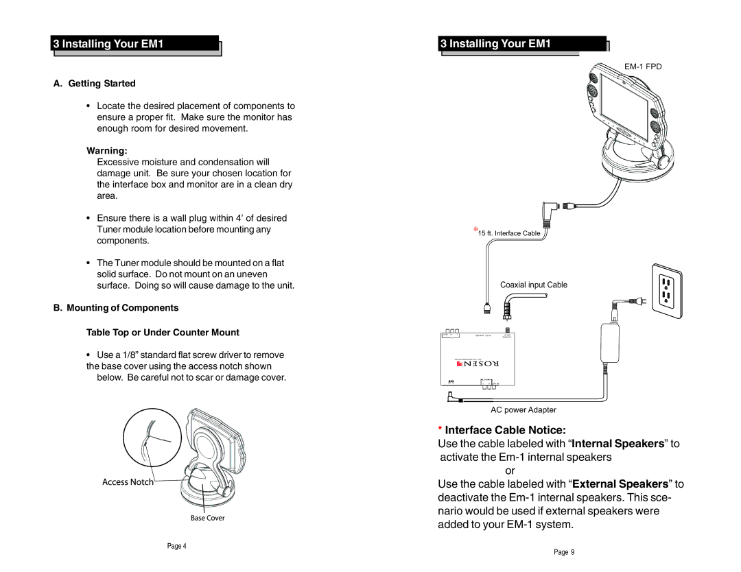
EM-1 FPD
*15 ft. Interface Cable
Coaxial input Cable
VIDEO | R | L | MONITOR OUT IR | IN .ANT |
|
|
| ||
| AV1 |
|
| EXTERNAL |
|
|
| ||
AC power Adapter
*Interface Cable Notice:
Use the cable labeled with “Internal Speakers” to activate the
or
Use the cable labeled with “External Speakers” to deactivate the
Page 9