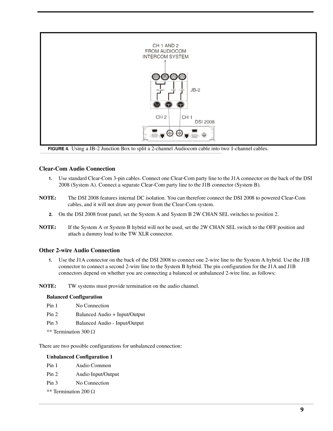
FIGURE 4. Using a JB-2 Junction Box to split a 2-channel Audiocom cable into two 1-channel cables.
Clear-Com Audio Connection
1.Use standard
NOTE: The DSI 2008 features internal DC isolation. You can therefore connect the DSI 2008 to powered
2.On the DSI 2008 front panel, set the System A and System B 2W CHAN SEL switches to position 2.
NOTE: If the System A or System B hybrid will not be used, set the 2W CHAN SEL switch to the OFF position and attach a dummy load to the TW XLR connector.
Other 2-wire Audio Connection
1.Use the J1A connector on the back of the DSI 2008 to connect one
NOTE: TW systems must provide termination on the audio channel.
Balanced Configuration
Pin 1 No Connection
Pin 2 Balanced Audio + Input/Output
Pin 3 Balanced Audio - Input/Output ** Termination 300 Ω
There are two possible configurations for unbalanced connection:
Unbalanced Configuration 1
Pin 1 Audio Common
Pin 2 Audio Input/Output
Pin 3 No Connection ** Termination 200 Ω
9