APPENDIX A
Access and Configuration
Internal Access
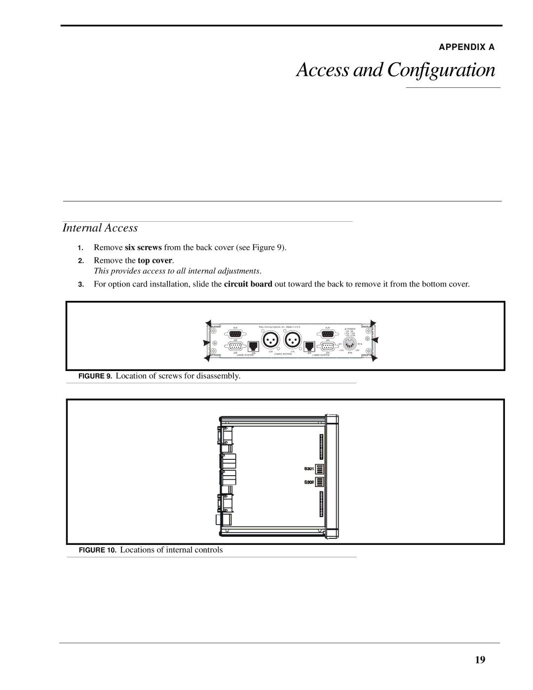
1.Remove six screws from the back cover (see Figure 9).
2.Remove the top cover.
This provides access to all internal adjustments.
3.For option card installation, slide the circuit board out toward the back to remove it from the bottom cover.
AUX | Telex Communications, Inc., Made in U.S.A. | ||
J4B |
|
| |
J3B | J1B | J1A | |
J2B | 2 WIRE SYSTEM | ||
4 WIRE SYSTEM | |||
| |||
AUX | J5 POWER | |
| +5V | 3A |
| +15V | 1.6A |
| ||
J4A
| +5V | RTN |
| +15V | |
J2A | J3A | RTN |
| 4 WIRE SYSTEM |
|
FIGURE 9. Location of screws for disassembly.
FIGURE 10. Locations of internal controls
19