2. RuggedBackbone™ Modules
2.1.1. Module Status LEDs
The front panel module status LEDs provide the following information:
LED |
| Purpose | Description |
|
|
| I = Power supply is receiving input voltage. |
PM |
| Indicates power supply status. | O = Power supply is providing |
|
|
| output voltage to the RX1512. |
|
|
|
|
|
|
| Green = OK |
LM 1 through 2 |
| Indicates the line module status. | Orange = Warning alert |
|
|
| Red = Configuration error |
|
|
|
|
Table 2.1. Module Status LED Indications |
|
| |
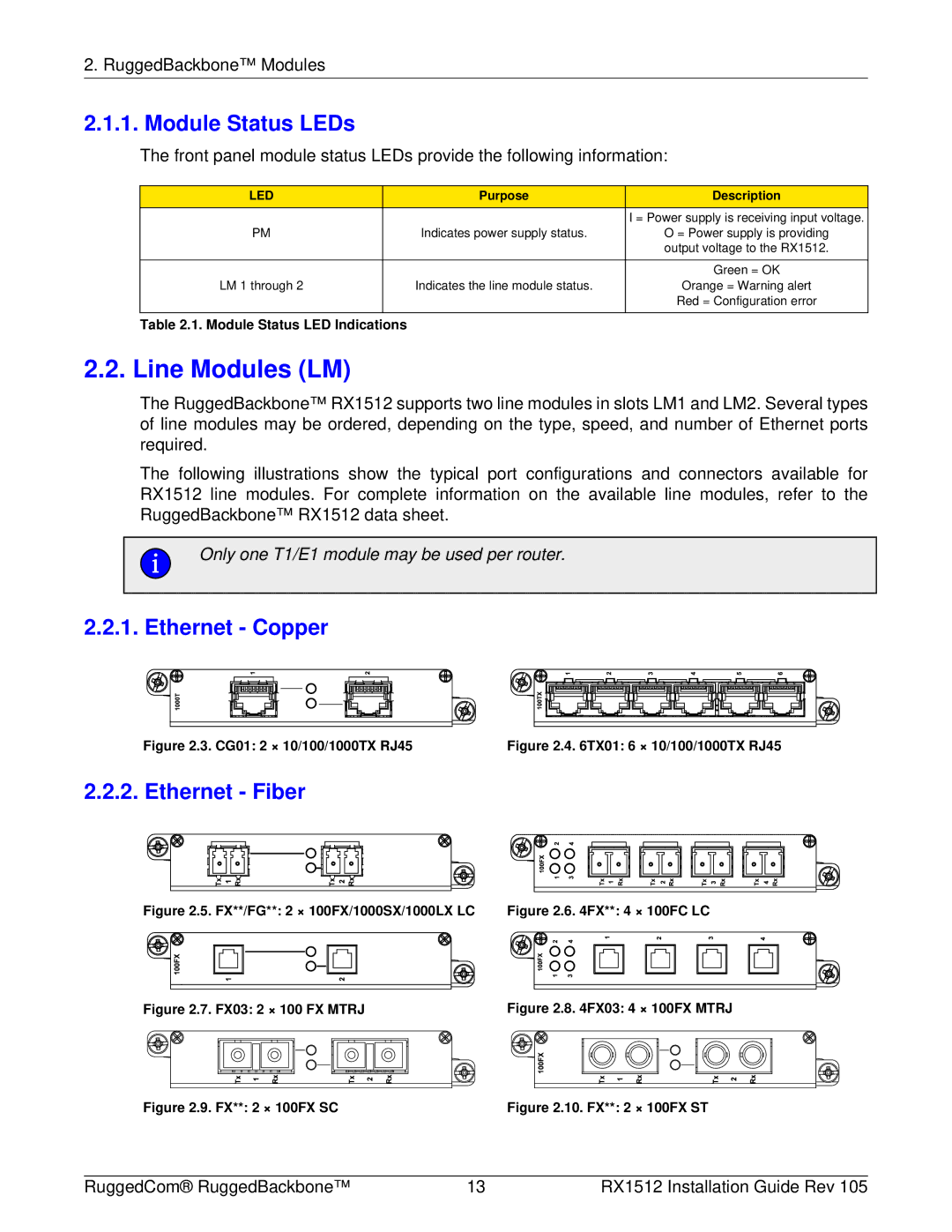
2.2. Line Modules (LM)
The RuggedBackbone™ RX1512 supports two line modules in slots LM1 and LM2. Several types of line modules may be ordered, depending on the type, speed, and number of Ethernet ports required.
The following illustrations show the typical port configurations and connectors available for RX1512 line modules. For complete information on the available line modules, refer to the RuggedBackbone™ RX1512 data sheet.
Only one T1/E1 module may be used per router.
2.2.1. Ethernet - Copper
Figure 2.3. CG01: 2 × 10/100/1000TX RJ45 | Figure 2.4. 6TX01: 6 × 10/100/1000TX RJ45 |
2.2.2. Ethernet - Fiber
Figure 2.5. FX**/FG**: 2 × 100FX/1000SX/1000LX LC | Figure 2.6. 4FX**: 4 × 100FC LC | ||||||||||||||||||||||||||||||
|
|
|
|
|
|
|
|
|
|
|
|
|
|
|
|
|
|
|
|
|
|
|
|
|
|
|
|
|
|
|
|
|
|
|
|
|
|
|
|
|
|
|
|
|
|
|
|
|
|
|
|
|
|
|
|
|
|
|
|
|
|
|
|
|
|
|
|
|
|
|
|
|
|
|
|
|
|
|
|
|
|
|
|
|
|
|
|
|
|
|
|
|
|
|
|
|
|
|
|
|
|
|
|
|
|
|
|
|
|
|
|
|
|
|
|
|
|
|
|
|
|
|
|
|
|
|
|
|
|
|
|
|
|
|
|
|
|
|
|
|
|
|
|
|
|
|
|
|
|
|
|
|
|
|
|
|
|
|
|
|
|
|
|
|
|
|
|
|
|
|
|
|
|
|
|
|
|
|
|
|
|
|
|
|
|
|
|
|
|
|
|
|
|
|
|
|
|
|
|
|
|
|
|
|
|
|
|
|
|
|
|
|
|
|
|
|
|
|
|
|
|
|
|
|
|
|
|
|
|
|
|
|
|
|
|
|
|
|
|
|
|
|
|
|
|
|
|
|
|
|
|
|
|
|
|
Figure 2.7. FX03: 2 × 100 FX MTRJ |
|
|
|
|
|
| Figure 2.8. 4FX03: 4 × 100FX MTRJ |
|
|
|
| ||||||||||||||||||||||
|
|
|
|
|
|
|
|
|
|
|
|
|
|
|
|
|
|
|
|
|
|
|
|
|
|
|
|
|
|
|
|
|
|
|
|
|
|
|
|
|
|
|
|
|
|
|
|
|
|
|
|
|
|
|
|
|
|
|
|
|
|
|
|
|
|
|
|
|
|
|
|
|
|
|
|
|
|
|
|
|
|
|
|
|
|
|
|
|
|
|
|
|
|
|
|
|
|
|
|
|
|
|
|
|
|
|
|
|
|
|
|
|
|
|
|
|
|
|
|
|
|
|
|
|
|
|
|
|
|
|
|
|
|
|
|
|
|
|
|
|
|
|
|
|
|
|
|
|
|
|
|
|
|
|
|
|
|
|
|
|
|
|
|
|
|
|
|
|
|
|
|
|
|
|
|
|
|
|
|
|
|
|
|
|
|
|
|
|
|
|
|
|
|
|
|
|
|
|
|
|
|
|
|
|
|
|
|
|
|
|
|
|
|
|
|
|
|
|
|
|
|
|
|
|
|
|
|
|
|
|
|
|
|
|
|
|
|
|
|
|
|
|
|
|
|
|
|
|
|
|
|
|
|
|
|
|
|
|
|
|
|
|
|
|
|
|
|
|
|
|
|
|
|
|
|
|
|
|
|
|
|
|
|
|
|
|
|
|
|
|
|
|
|
|
|
|
|
|
|
|
|
|
|
|
|
Figure 2.9. FX**: 2 × 100FX SC | Figure 2.10. FX**: 2 × 100FX ST |
RuggedCom® RuggedBackbone™ | 13 | RX1512 Installation Guide Rev 105 |