3. Installation
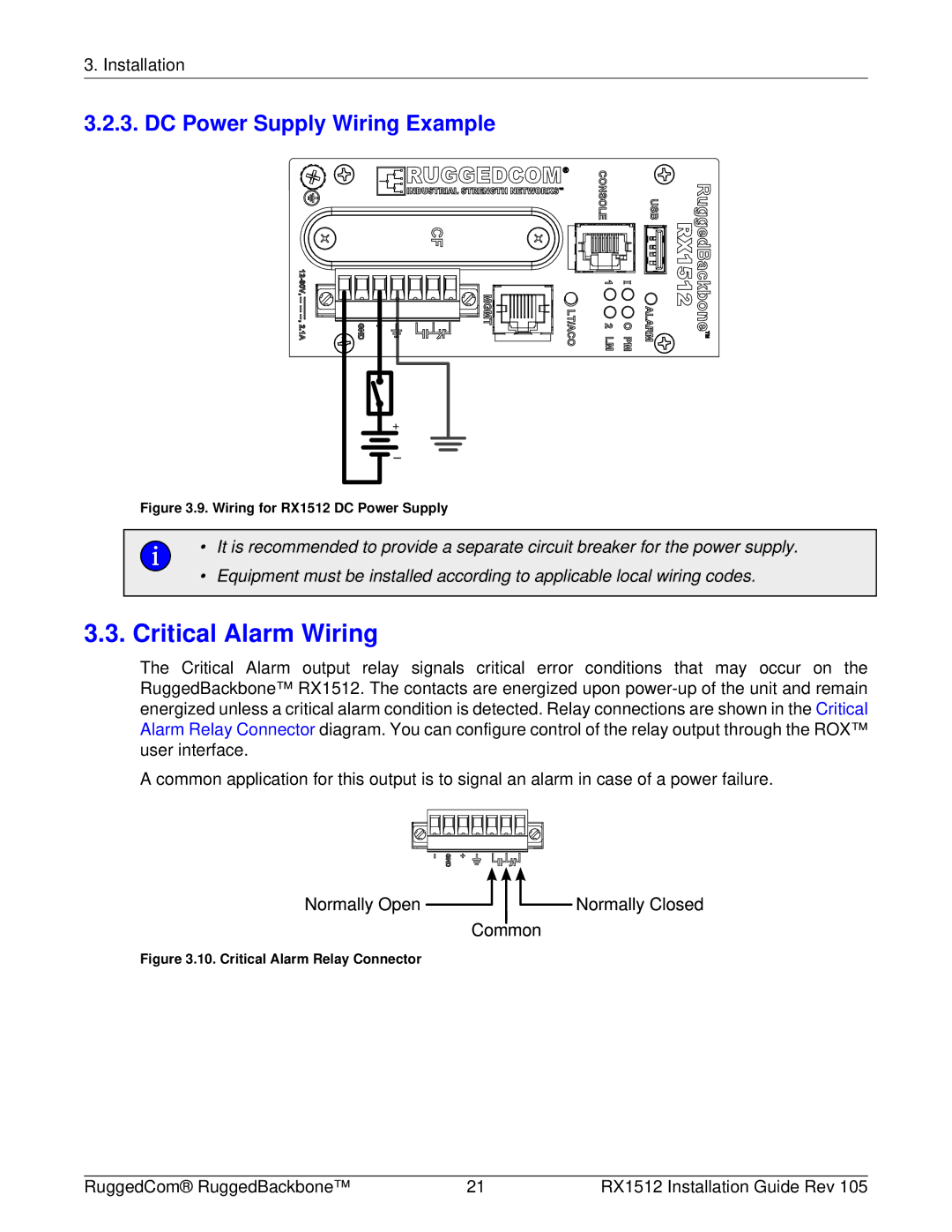
3.2.3. DC Power Supply Wiring Example
+
Figure 3.9. Wiring for RX1512 DC Power Supply
• It is recommended to provide a separate circuit breaker for the power supply.
•Equipment must be installed according to applicable local wiring codes.
3.3.Critical Alarm Wiring
The Critical Alarm output relay signals critical error conditions that may occur on the RuggedBackbone™ RX1512. The contacts are energized upon
A common application for this output is to signal an alarm in case of a power failure.
Figure 3.10. Critical Alarm Relay Connector
RuggedCom® RuggedBackbone™ | 21 | RX1512 Installation Guide Rev 105 |