2. WIRING
Wiring
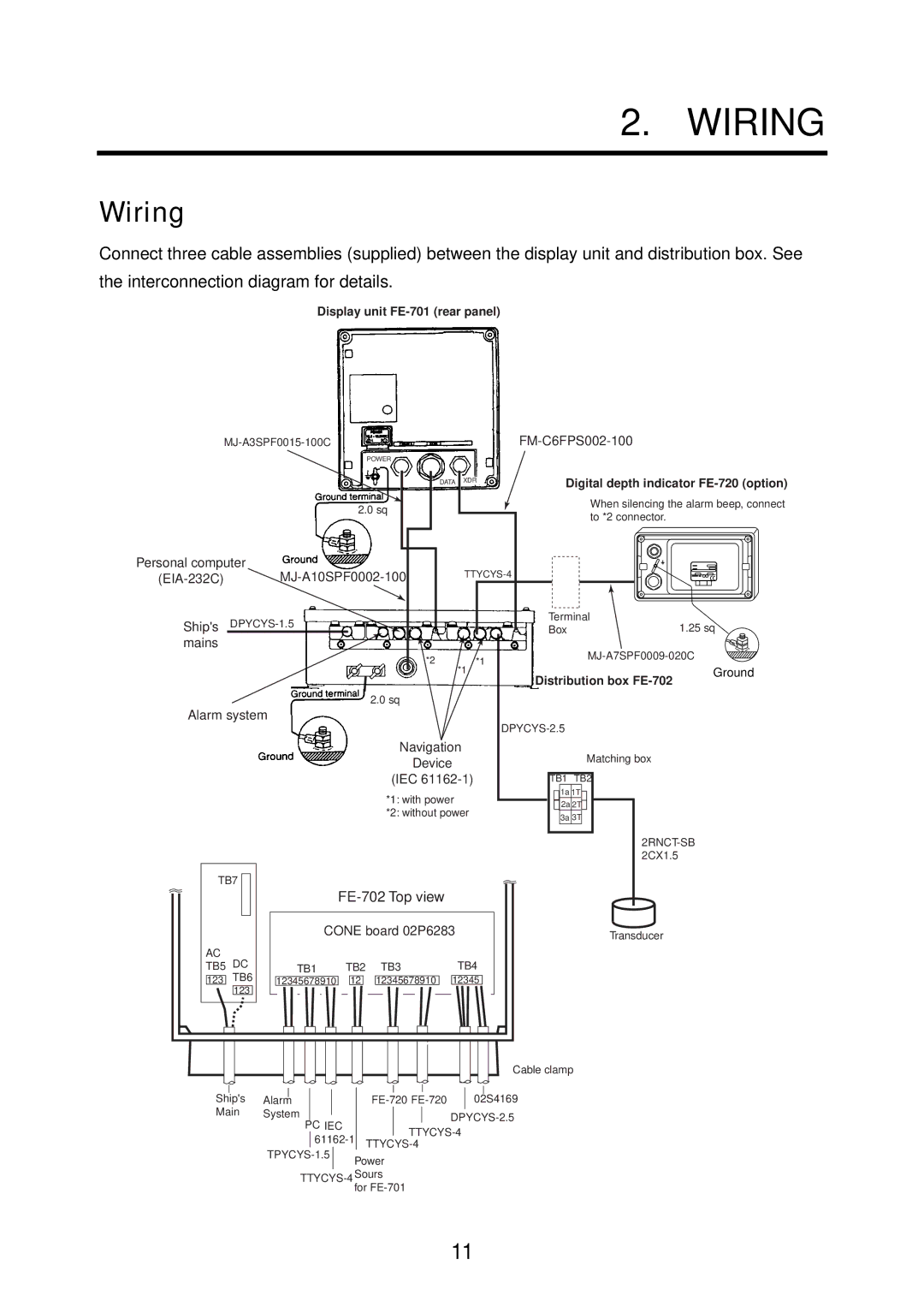
Connect three cable assemblies (supplied) between the display unit and distribution box. See the interconnection diagram for details.
Display unit FE-701 (rear panel)
|
|
|
|
| |
| POWER |
|
|
|
|
|
| DATA XDR | Digital depth indicator | ||
|
|
|
| ||
| 2.0 sq |
|
| When silencing the alarm beep, connect | |
|
|
| to *2 connector. |
| |
|
|
|
|
| |
Personal computer |
| ||||
| |||||
|
|
|
| ||
Ship's |
|
| Terminal | 1.25 sq | |
|
| Box | |||
mains |
|
|
| ||
|
| *2 | *1 | ||
|
|
|
| ||
|
| *1 |
| Distribution box | Ground |
|
|
|
|
| |
| 2.0 sq |
|
|
|
|
Alarm system |
|
|
| ||
|
|
|
|
| |
| Navigation |
| Matching box |
| |
|
| Device |
|
| |
| (IEC |
| TB1 TB2 |
| |
| *1: with power |
| 1a 1T |
| |
|
| 2a 2T |
| ||
| *2: without power |
|
| ||
|
| 3a 3T |
| ||
|
|
|
|
| |
TB7 |
|
|
|
|
|
|
|
|
|
| |
| CONE board 02P6283 | Transducer | |||
|
|
|
|
| |
AC |
|
|
|
|
|
TB5 DC | TB1 | TB2 | TB3 | TB4 |
|
123 TB6 | 12345678910 | 12 | 12345678910 | 12345 |
|
123 |
|
|
|
|
|
|
|
|
|
| Cable clamp |
|
|
|
|
|
|
|
|
|
|
|
|
|
|
|
Ship's | Alarm |
|
|
|
|
|
|
| 02S4169 | |||||
Main | System |
|
|
|
|
|
|
|
|
|
| |||
|
|
|
|
|
|
| ||||||||
|
|
|
|
|
|
| ||||||||
|
|
|
|
| PC IEC |
|
| |||||||
|
|
|
|
|
|
| ||||||||
|
|
|
|
|
|
|
|
| ||||||
|
|
|
|
|
|
|
|
|
|
|
| |||
|
|
| Power |
|
|
| ||||||||
|
|
|
|
|
|
|
|
|
|
| ||||
|
|
|
|
| TTYCYS |
|
|
| ||||||
|
|
|
|
|
|
|
| for |
|
|
| |||
11