3. Installation
3.2. Power Supply Wiring and Grounding
The RX1512 features a Phoenix Plug Terminal Block. Both DC power supply and
For DC power supply wiring examples, refer to Section 3.2.3, “DC Power Supply WiringExample ”.
For
The RX1512 has one (1) power supply installed. Service personnel must isolate all power supplies prior to servicing.
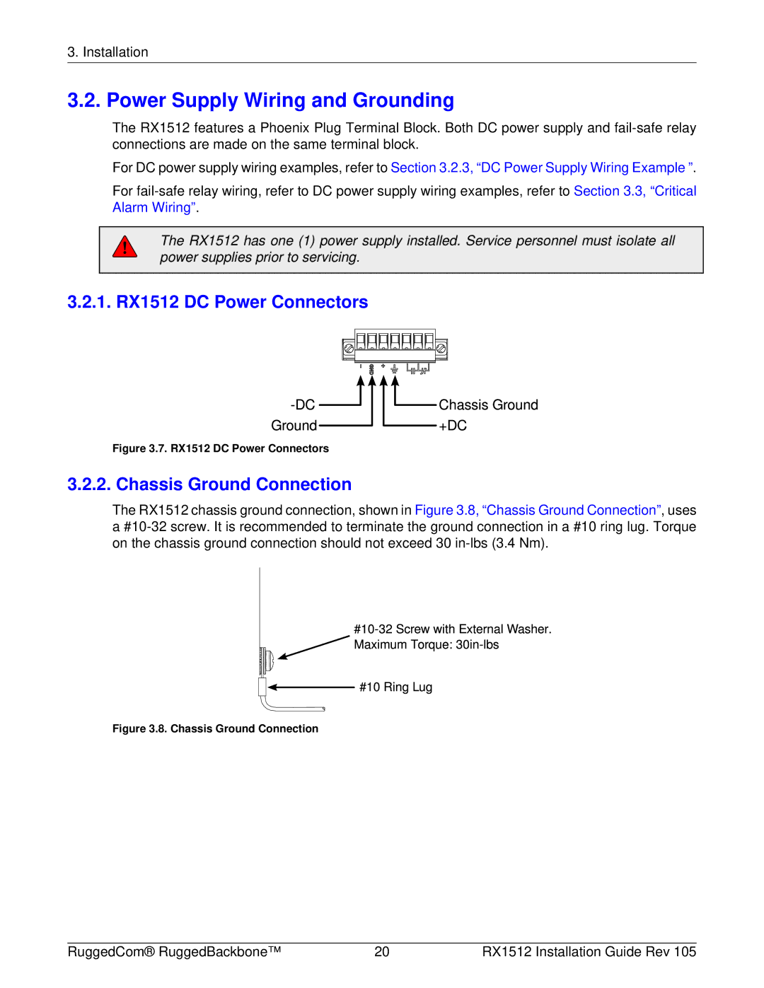
3.2.1. RX1512 DC Power Connectors
Figure 3.7. RX1512 DC Power Connectors
3.2.2. Chassis Ground Connection
The RX1512 chassis ground connection, shown in Figure 3.8, “Chassis Ground Connection”, uses a
Figure 3.8. Chassis Ground Connection
RuggedCom® RuggedBackbone™ | 20 | RX1512 Installation Guide Rev 105 |