3. Installation
3.8. Serial Ports: RJ45
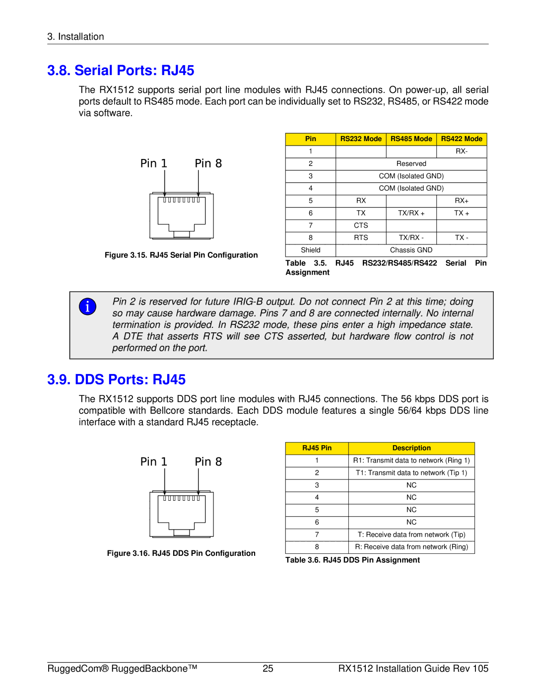
The RX1512 supports serial port line modules with RJ45 connections. On
|
|
|
|
|
|
|
|
|
|
|
|
|
|
|
| Pin | RS232 Mode | RS485 Mode | RS422 Mode |
| 1 |
|
| RX- | |||||||||||||||
|
|
|
|
| |||||||||||||||
| 2 |
| Reserved |
| |||||||||||||||
|
|
|
|
|
| ||||||||||||||
|
|
|
|
|
|
|
|
|
|
|
|
| 3 | COM (Isolated GND) | |||||
|
|
|
|
| |||||||||||||||
|
|
|
|
|
|
|
|
|
|
|
|
|
| 4 | COM (Isolated GND) | ||||
|
|
|
|
|
|
|
|
|
|
|
|
|
|
|
|
|
| ||
|
|
|
|
|
|
|
|
|
|
|
|
|
|
|
| 5 | RX |
| RX+ |
|
|
|
|
|
|
|
|
|
|
|
|
|
|
|
|
| |||
|
|
|
|
|
|
|
|
|
|
|
|
|
|
|
| ||||
|
|
|
|
|
|
|
|
|
|
|
|
|
|
|
|
|
| ||
|
|
|
|
|
|
|
|
|
|
|
|
|
|
|
| 6 | TX | TX/RX + | TX + |
|
|
|
|
|
|
|
|
|
|
|
|
|
|
|
|
|
| ||
|
|
|
|
|
|
|
|
|
|
|
|
|
|
|
| 7 | CTS |
|
|
|
|
|
|
|
|
|
|
|
|
|
|
|
|
|
|
| |||
|
|
|
|
|
|
|
|
|
|
|
|
|
|
|
|
|
|
|
|
|
|
|
|
|
|
|
|
|
|
|
|
|
|
|
| 8 | RTS | TX/RX - | TX - |
|
|
|
|
|
|
|
|
|
|
|
|
|
|
| |||||
|
|
|
|
|
|
|
|
|
|
|
|
|
|
| |||||
|
|
|
|
|
|
|
|
|
|
|
|
|
|
|
|
|
|
|
|
Figure 3.15. RJ45 Serial Pin Configuration | Shield |
| Chassis GND |
| |||||||||||||||
|
|
|
| ||||||||||||||||
|
|
|
| ||||||||||||||||
Table 3.5. RJ45 RS232/RS485/RS422 Serial Pin
Assignment
Pin 2 is reserved for future
3.9. DDS Ports: RJ45
The RX1512 supports DDS port line modules with RJ45 connections. The 56 kbps DDS port is compatible with Bellcore standards. Each DDS module features a single 56/64 kbps DDS line interface with a standard RJ45 receptacle.
RJ45 Pin | Description |
1 | R1: Transmit data to network (Ring 1) |
|
|
2 | T1: Transmit data to network (Tip 1) |
|
|
3 | NC |
|
|
4 | NC |
|
|
5 | NC |
|
|
6 | NC |
|
|
7 | T: Receive data from network (Tip) |
|
|
8 | R: Receive data from network (Ring) |
Figure 3.16. RJ45 DDS Pin Configuration
Table 3.6. RJ45 DDS Pin Assignment
RuggedCom® RuggedBackbone™ | 25 | RX1512 Installation Guide Rev 105 |
