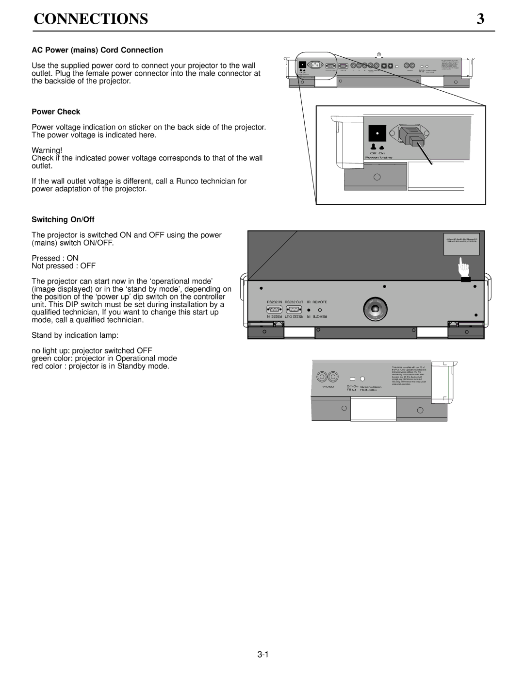
DTV-992 specifications
The Runco DTV-992 is a high-performance DLP projector that has garnered attention for its superior image quality and advanced features, making it a popular choice among home theater enthusiasts and professionals alike. With a focus on delivering an exceptional viewing experience, the DTV-992 showcases Runco's commitment to innovation and excellence in display technology.One of the standout features of the DTV-992 is its impressive resolution. The projector supports full HD 1080p, allowing for stunningly detailed images that bring content to life. This resolution, combined with the projector's high brightness output, ensures that it performs well even in well-lit environments, providing flexibility for various viewing conditions.
The DTV-992 incorporates advanced DLP (Digital Light Processing) technology, which enhances image clarity and color accuracy. This technology minimizes the issues associated with traditional LCD projectors, such as motion blurring or color distortion, resulting in an incredibly smooth and vibrant visual experience. The projector also supports a wide color gamut, ensuring that colors are rich and true to life, further enhancing the overall viewing experience.
In terms of installation and connectivity, the DTV-992 offers multiple input options, including HDMI and component video connections. This versatility allows it to seamlessly integrate with various sources, from Blu-ray players to gaming consoles. Additionally, it includes features such as lens shift and zoom, making it easier to position the projector within a room and tailor the image to the desired screen size.
Runco has also placed an emphasis on user-friendliness in the DTV-992. The projector includes an intuitive interface and remote control, allowing users to easily navigate settings and make adjustments. The integration of advanced image processing technologies further optimizes performance, providing enhanced sharpness and contrast for a more immersive viewing experience.
With a sleek and modern design, the DTV-992 fits well into any home theater setup, providing not only outstanding performance but also aesthetic appeal. Whether for movie nights, sports events, or gaming sessions, the Runco DTV-992 delivers a combination of stunning visuals and advanced features that elevate the home entertainment experience to new heights. Its cutting-edge technology, superior image quality, and user-friendly design make it a top contender in the high-end projector market.

