ASSEMBLY
![]() WARNING:
WARNING:
Do not connect to power supply until assembly is complete. Failure to comply could result in accidental starting and possible serious injury.
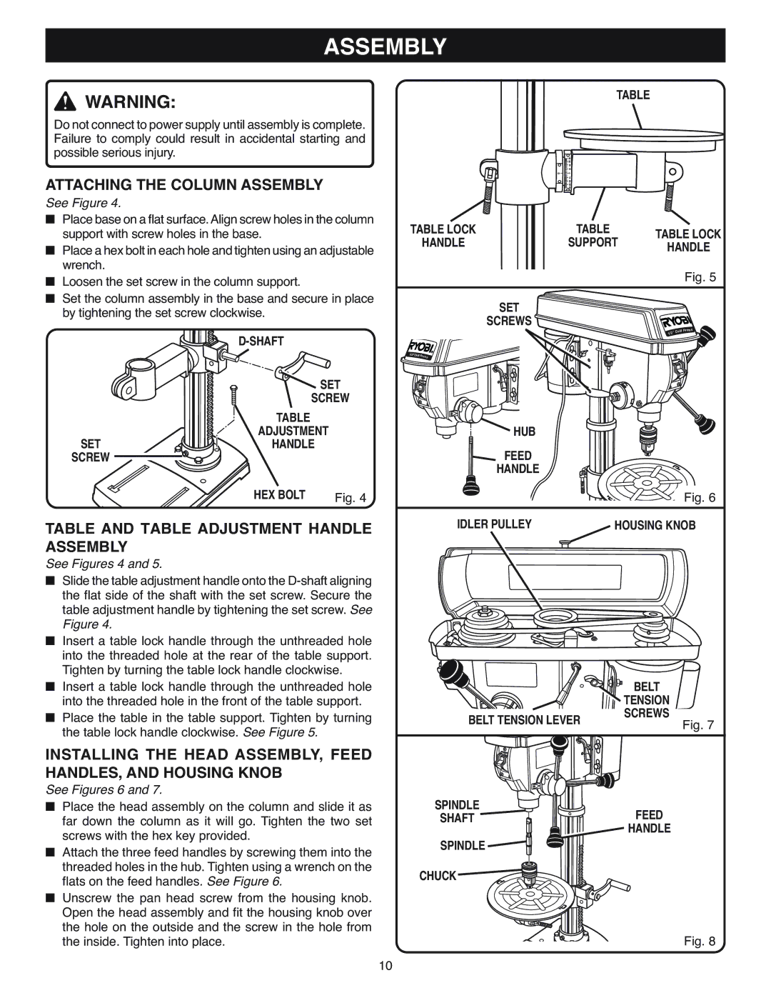
ATTACHING THE COLUMN ASSEMBLY
See Figure 4.
■Place base on a flat surface.Align screw holes in the column support with screw holes in the base.
■Place a hex bolt in each hole and tighten using an adjustable wrench.
■Loosen the set screw in the column support.
■Set the column assembly in the base and secure in place by tightening the set screw clockwise.
TABLE
| 40 30 |
| 20 |
| 10 |
0 | 0 |
| 10 |
| 20 |
| 30 |
| 40 |
TABLE LOCK | TABLE | TABLE LOCK | |
HANDLE | SUPPORT | ||
HANDLE | |||
|
| ||
|
| Fig. 5 | |
| SET |
| |
| SCREWS |
|
| |
| SET |
| SCREW |
| TABLE |
SET | ADJUSTMENT |
HANDLE | |
SCREW |
|
1 | 2 |
Drill
1/2”
Press
ON
HUB
FEED
HANDLE
Drill
Press
HEX BOLT | Fig. 4 |
TABLE AND TABLE ADJUSTMENT HANDLE ASSEMBLY
See Figures 4 and 5.
■Slide the table adjustment handle onto the
■Insert a table lock handle through the unthreaded hole into the threaded hole at the rear of the table support. Tighten by turning the table lock handle clockwise.
■Insert a table lock handle through the unthreaded hole into the threaded hole in the front of the table support.
■Place the table in the table support. Tighten by turning the table lock handle clockwise. See Figure 5.
INSTALLING THE HEAD ASSEMBLY, FEED HANDLES, AND HOUSING KNOB
See Figures 6 and 7.
■Place the head assembly on the column and slide it as far down the column as it will go. Tighten the two set screws with the hex key provided.
■Attach the three feed handles by screwing them into the threaded holes in the hub. Tighten using a wrench on the flats on the feed handles. See Figure 6.
■Unscrew the pan head screw from the housing knob. Open the head assembly and fit the housing knob over the hole on the outside and the screw in the hole from the inside. Tighten into place.
Fig. 6
IDLER PULLEY | HOUSING KNOB |
| BELT | |
| TENSION | |
BELT TENSION LEVER | SCREWS | |
Fig. 7 | ||
| ||
ON |
| |
SPINDLE | FEED | |
SHAFT | ||
| HANDLE | |
SPINDLE |
| |
CHUCK |
|
Fig. 8
10