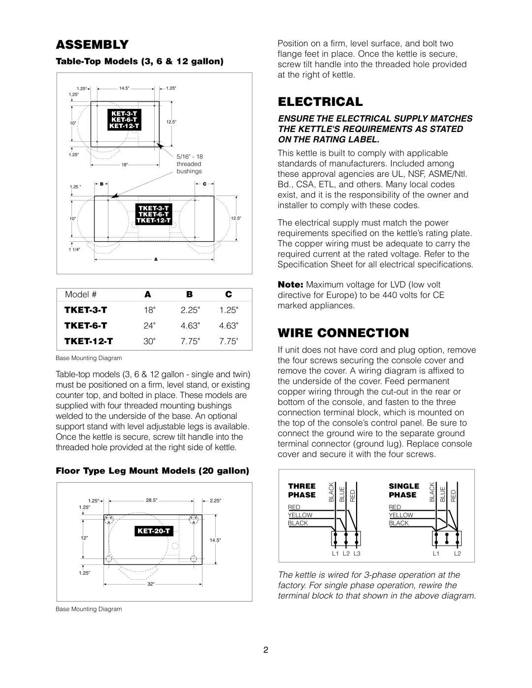
ASSEMBLY |
|
|
| ||
1.25" |
| 14.5" | 1.25" |
|
|
1.25" |
|
|
|
|
|
|
|
|
|
| |
10" |
| 12.5" |
|
| |
|
|
|
| ||
1.25" |
|
|
| 5/16" - 18 |
|
|
|
|
|
| |
|
| 18" |
| threaded |
|
|
|
|
| bushings |
|
1.25 " | B |
|
|
| C |
|
|
|
|
| |
|
|
|
|
| |
10" |
|
|
| 12.5" | |
|
| ||||
|
|
|
| ||
1 1/4" |
|
|
|
|
|
|
|
| A |
|
|
Model # |
|
| A | B | C |
|
| 18" | 2.25" | 1.25" | |
|
| 24" | 4.63" | 4.63" | |
| 30" | 7.75" | 7.75" | ||
Base Mounting Diagram
Floor Type Leg Mount Models (20 gallon)
1.25" | 28.5" | 2.25" |
1.25" |
|
|
|
| |
12" |
| 14.5" |
|
| |
1.25" |
|
|
| 32" |
|
Base Mounting Diagram
Position on a firm, level surface, and bolt two flange feet in place. Once the kettle is secure, screw tilt handle into the threaded hole provided at the right of kettle.
ELECTRICAL
ENSURE THE ELECTRICAL SUPPLY MATCHES THE KETTLE'S REQUIREMENTS AS STATED ON THE RATING LABEL.
This kettle is built to comply with applicable standards of manufacturers. Included among these approval agencies are UL, NSF, ASME/Ntl. Bd., CSA, ETL, and others. Many local codes exist, and it is the responsibility of the owner and installer to comply with these codes.
The electrical supply must match the power requirements specified on the kettle’s rating plate. The copper wiring must be adequate to carry the required current at the rated voltage. Refer to the Specification Sheet for all electrical specifications.
Note: Maximum voltage for LVD (low volt directive for Europe) to be 440 volts for CE marked appliances.
WIRE CONNECTION
If unit does not have cord and plug option, remove the four screws securing the console cover and remove the cover. A wiring diagram is affixed to the underside of the cover. Feed permanent copper wiring through the
THREE | BLACK |
| BLUE |
| RED |
| SINGLE | BLACK | BLUE | RED |
| ||||
|
|
|
| ||||||||||||
|
|
|
|
|
|
|
|
|
|
|
|
|
| ||
PHASE |
|
|
|
|
|
|
| PHASE |
|
|
|
|
|
|
|
RED |
|
|
|
|
|
|
| RED |
|
|
|
|
|
|
|
YELLOW |
|
|
|
|
|
|
| YELLOW |
|
|
|
|
|
|
|
BLACK |
|
|
|
|
|
|
| BLACK |
|
|
|
|
|
|
|
|
|
|
|
|
|
|
|
|
|
|
|
|
|
|
|
|
|
|
|
|
|
|
|
|
|
|
|
|
|
|
|
|
|
|
|
|
|
|
|
|
|
|
|
|
|
|
|
|
| L1 | L2 | L3 |
|
| L1 |
| L2 |
| |||||
|
|
|
|
|
|
|
|
|
|
|
|
|
|
|
|
The kettle is wired for
2