OPERATION
![]() WARNING:
WARNING:
Your router should never be connected to power supply when you are assembling parts, making adjustments, installing or removing cutters, or when not in use. Disconnecting your router will prevent accidental starting that could cause serious injury.
INSTALLING/REMOVING CUTTERS
See Figures 2 and 3.
1.UNPLUG YOUR ROUTER.
![]() WARNING:
WARNING:
Failure to unplug your router could result in accidental starting causing serious injury.
![]() WARNING:
WARNING:
To prevent damage to the spindle or spindle lock, always allow motor to come to a complete stop before engaging spindle lock.
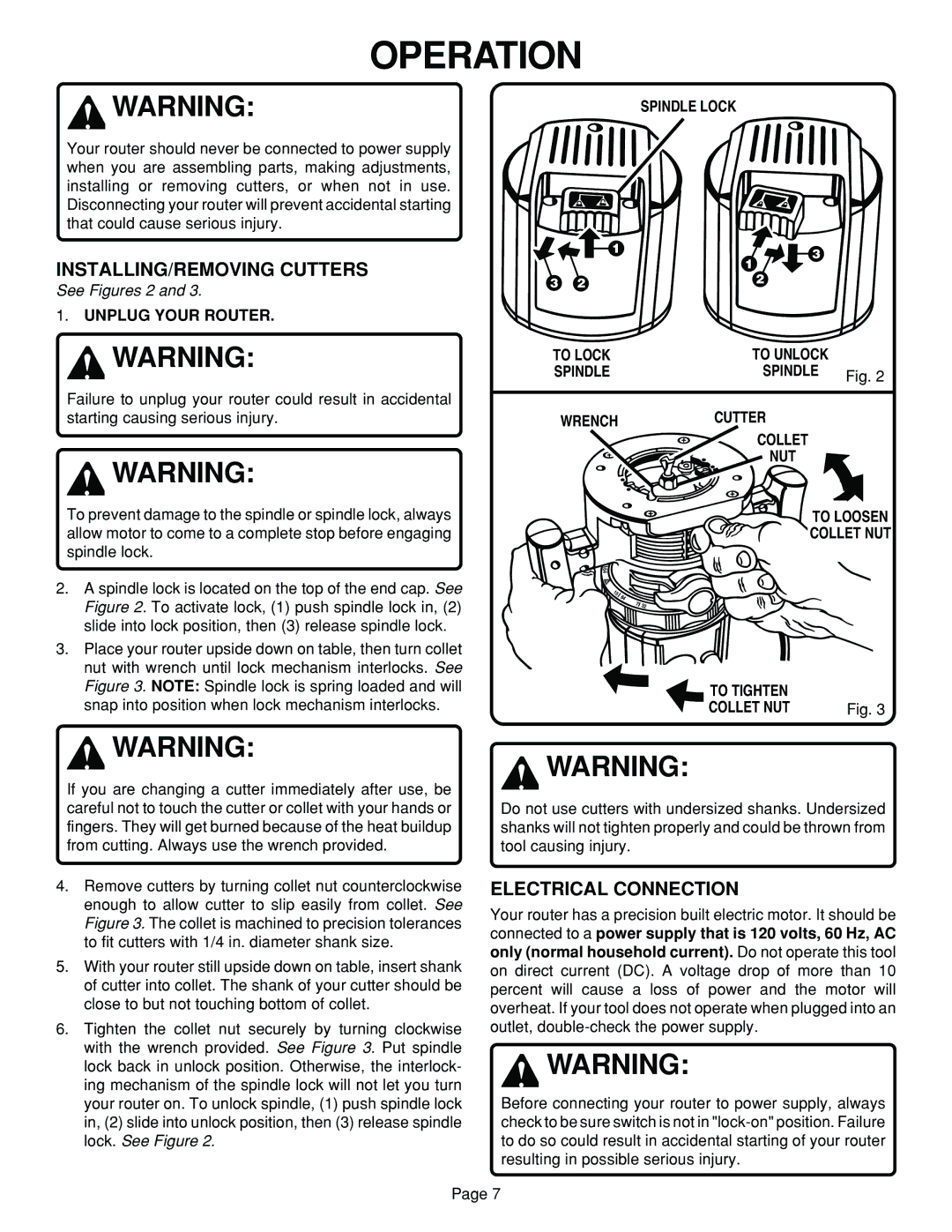
2.A spindle lock is located on the top of the end cap. See Figure 2. To activate lock, (1) push spindle lock in, (2) slide into lock position, then (3) release spindle lock.
3.Place your router upside down on table, then turn collet nut with wrench until lock mechanism interlocks. See Figure 3. NOTE: Spindle lock is spring loaded and will snap into position when lock mechanism interlocks.
SPINDLE LOCK
1 | 3 |
| 1 |
3 | 2 | 2 |
|
TO LOCK | TO UNLOCK |
|
SPINDLE | SPINDLE | Fig. 2 |
|
| |
WRENCH | CUTTER |
|
| COLLET |
|
| NUT |
|
| TO LOOSEN | |
| COLLET NUT | |
64
0
1 |
|
5 | 64 |
|
7 | 32 |
TO TIGHTEN |
|
COLLET NUT | Fig. 3 |
![]() WARNING:
WARNING:
If you are changing a cutter immediately after use, be careful not to touch the cutter or collet with your hands or fingers. They will get burned because of the heat buildup from cutting. Always use the wrench provided.
4.Remove cutters by turning collet nut counterclockwise enough to allow cutter to slip easily from collet. See Figure 3. The collet is machined to precision tolerances to fit cutters with 1/4 in. diameter shank size.
5.With your router still upside down on table, insert shank of cutter into collet. The shank of your cutter should be close to but not touching bottom of collet.
6.Tighten the collet nut securely by turning clockwise with the wrench provided. See Figure 3. Put spindle lock back in unlock position. Otherwise, the interlock- ing mechanism of the spindle lock will not let you turn your router on. To unlock spindle, (1) push spindle lock in, (2) slide into unlock position, then (3) release spindle lock. See Figure 2.
![]() WARNING:
WARNING:
Do not use cutters with undersized shanks. Undersized shanks will not tighten properly and could be thrown from tool causing injury.
ELECTRICAL CONNECTION
Your router has a precision built electric motor. It should be connected to a power supply that is 120 volts, 60 Hz, AC only (normal household current). Do not operate this tool on direct current (DC). A voltage drop of more than 10 percent will cause a loss of power and the motor will overheat. If your tool does not operate when plugged into an outlet,
![]() WARNING:
WARNING:
Before connecting your router to power supply, always check to be sure switch is not in
Page 7