ADJUSTMENTS
SQUARING THE MITER TABLE TO THE FENCE
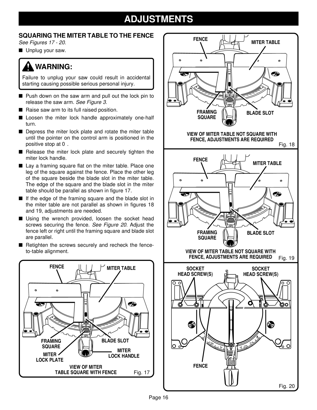
See Figures 17 - 20.
■Unplug your saw.
![]() WARNING:
WARNING:
Failure to unplug your saw could result in accidental starting causing possible serious personal injury.
■Push down on the saw arm and pull out the lock pin to
release the saw arm. See Figure 3.
■ Raise saw arm to its full raised position. |
■ Loosen the miter lock handle approximately |
turn. |
■ Depress the miter lock plate and rotate the miter table |
until the pointer on the control arm is positioned in the |
FENCE
MITER TABLE
1 | 2 | 3 | 4 | 5 | 6 | 7 | 8 |
FRAMING | BLADE SLOT |
SQUARE |
|
VIEW OF MITER TABLE NOT SQUARE WITH FENCE, ADJUSTMENTS ARE REQUIRED
positive stop at 0° . |
■ Release the miter lock plate and securely tighten the |
miter lock handle. |
■ Lay a framing square flat on the miter table. Place one |
leg of the square against the fence. Place the other leg |
of the square beside the blade slot in the miter table. |
FENCE
Fig. 18
MITER TABLE
The edge of the square and the blade slot in the miter |
table should be parallel as shown in figure 17. |
■ If the edge of the framing square and the blade slot in |
the miter table are not parallel as shown in figures 18 |
and 19, adjustments are needed. |
■ Using the wrench provided, loosen the socket head |
screws securing the fence. See Figure 20. Adjust the |
fence left or right until the framing square and blade slot |
are parallel. |
■ Retighten the screws securely and recheck the fence- |
FENCE | MITER TABLE |
1 | 2 | 3 | 4 | 5 | 6 | 7 | 8 |
FRAMING | BLADE SLOT |
|
SQUARE | MITER |
|
MITER |
| |
LOCK HANDLE | ||
LOCK PLATE |
|
|
| VIEW OF MITER |
|
TABLE SQUARE WITH FENCE | Fig. 17 | |
Page 16
1 | 2 | 3 | 4 | 5 | 6 | 7 | 8 |
FRAMING | BLADE SLOT |
SQUARE |
|
VIEW OF MITER TABLE NOT SQUARE WITH FENCE, ADJUSTMENTS ARE REQUIRED Fig. 19
SOCKET | SOCKET |
HEAD SCREW(S) | HEAD SCREW(S) |
5 |
|
| 5 |
4 |
| 4 |
|
31.6 |
| 31 |
|
| 30 | .6 |
|
|
|
| |
| 15 | 22.5 |
|
| 15 |
|
FENCE
Fig. 20
