FEATURES
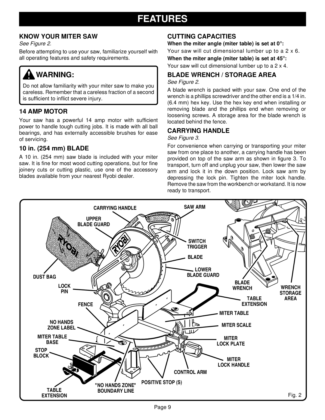
KNOW YOUR MITER SAW
See Figure 2.
Before attempting to use your saw, familiarize yourself with all operating features and safety requirements.
CUTTING CAPACITIES
When the miter angle (miter table) is set at 0° :
Your saw will cut dimensional lumber up to a 2 x 6.
When the miter angle (miter table) is set at 45° :
Your saw will cut dimensional lumber up to a 2 x 4.
![]() WARNING:
WARNING:
Do not allow familiarity with your miter saw to make you careless. Remember that a careless fraction of a second is sufficient to inflict severe injury.
14 AMP MOTOR
Your saw has a powerful 14 amp motor with sufficient power to handle tough cutting jobs. It is made with all ball bearings, and has externally accessible brushes for ease of servicing.
10 in. (254 mm) BLADE
A 10 in. (254 mm) saw blade is included with your miter saw. It is fine for most wood cutting operations, but for fine joinery cuts or cutting plastic, use one of the accessory blades available from your nearest Ryobi dealer.
BLADE WRENCH / STORAGE AREA
See Figure 2.
A blade wrench is packed with your saw. One end of the wrench is a phillips screwdriver and the other end is a 1/4 in. (6.4 mm) hex key. Use the hex key end when installing or removing blade and the phillips end when removing or loosening screws. A storage area for the blade wrench is located behind the fence.
CARRYING HANDLE
See Figure 3.
For convenience when carrying or transporting your miter saw from one place to another, a carrying handle has been provided on top of the saw arm as shown in figure 3. To transport, turn off and unplug your saw, then lower the saw arm and lock it in the down position. Lock saw arm by depressing the lock pin. Tighten the miter lock handle. Remove the saw from the workbench or workstand. It is now ready to transport.
CARRYING HANDLE | SAW ARM |
UPPER
BLADE GUARD
DUST BAG
LOCK
PIN
FENCE
NO HANDS
ZONE LABEL
MITER TABLE
BASE
STOP
BLOCK
"NO HANDS ZONE"
TABLEBOUNDARY LINE EXTENSION
SWITCH
TRIGGER
| BLADE |
|
| LOWER |
|
| BLADE GUARD |
|
| BLADE | WRENCH |
| WRENCH | |
|
| STORAGE |
8 | TABLE | AREA |
5 | EXTENSION |
|
4 |
|
|
3 | MITER TABLE |
|
1 |
| |
2 |
|
|
MITER SCALE
MITER
LOCK PLATE
MITER
LOCK HANDLE
CONTROL ARM
POSITIVE STOP (S)
Fig. 2
Page 9
