Guided Tour - UT1L / UT1G
4
LOW MID HIGH
BATT AUDIO
|
|
|
|
|
|
|
|
|
|
|
|
|
|
|
|
1 |
|
| 2 |
|
| 3 | |
|
|
|
|
|
|
|
|
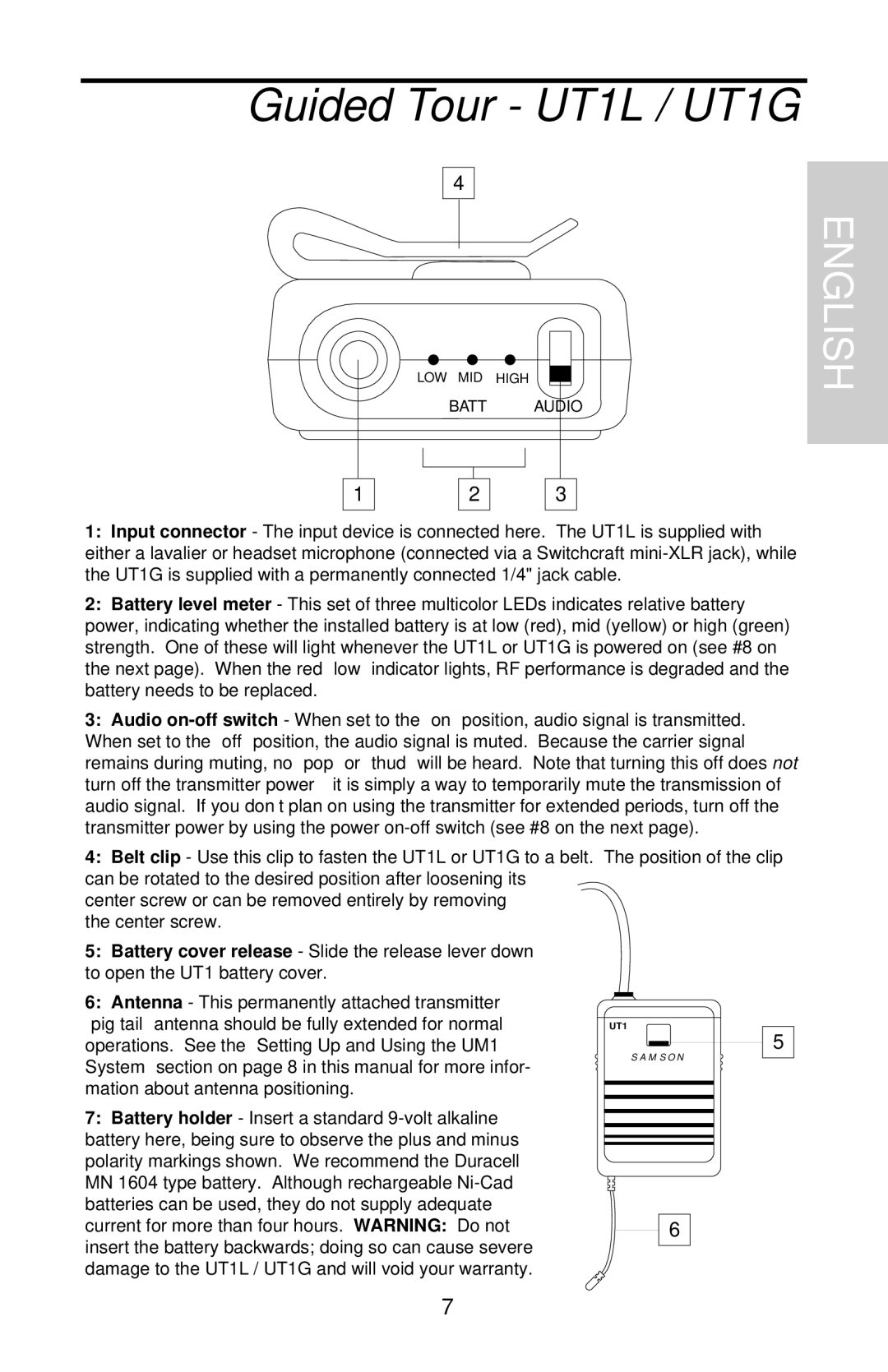
1:Input connector - The input device is connected here. The UT1L is supplied with either a lavalier or headset microphone (connected via a Switchcraft
2:Battery level meter - This set of three multicolor LEDs indicates relative battery power, indicating whether the installed battery is at low (red), mid (yellow) or high (green) strength. One of these will light whenever the UT1L or UT1G is powered on (see #8 on the next page). When the red “low” indicator lights, RF performance is degraded and the battery needs to be replaced.
3:Audio
4:Belt clip - Use this clip to fasten the UT1L or UT1G to a belt. The position of the clip can be rotated to the desired position after loosening its
center screw or can be removed entirely by removing the center screw.
ENGLISH
5:Battery cover release - Slide the release lever down to open the UT1 battery cover.
6:Antenna - This permanently attached transmitter “pig tail” antenna should be fully extended for normal operations. See the “Setting Up and Using the UM1 System” section on page 8 in this manual for more infor- mation about antenna positioning.
7:Battery holder - Insert a standard
UT1
5
SAMSON
6
7
