Guided Tour - UM1
ENGLISH
8 | 9 | 10 | 11 | ||
| DC INPUT | OUT UNBAL |
| LEVEL | |
|
|
| 30 | 20 | 10 |
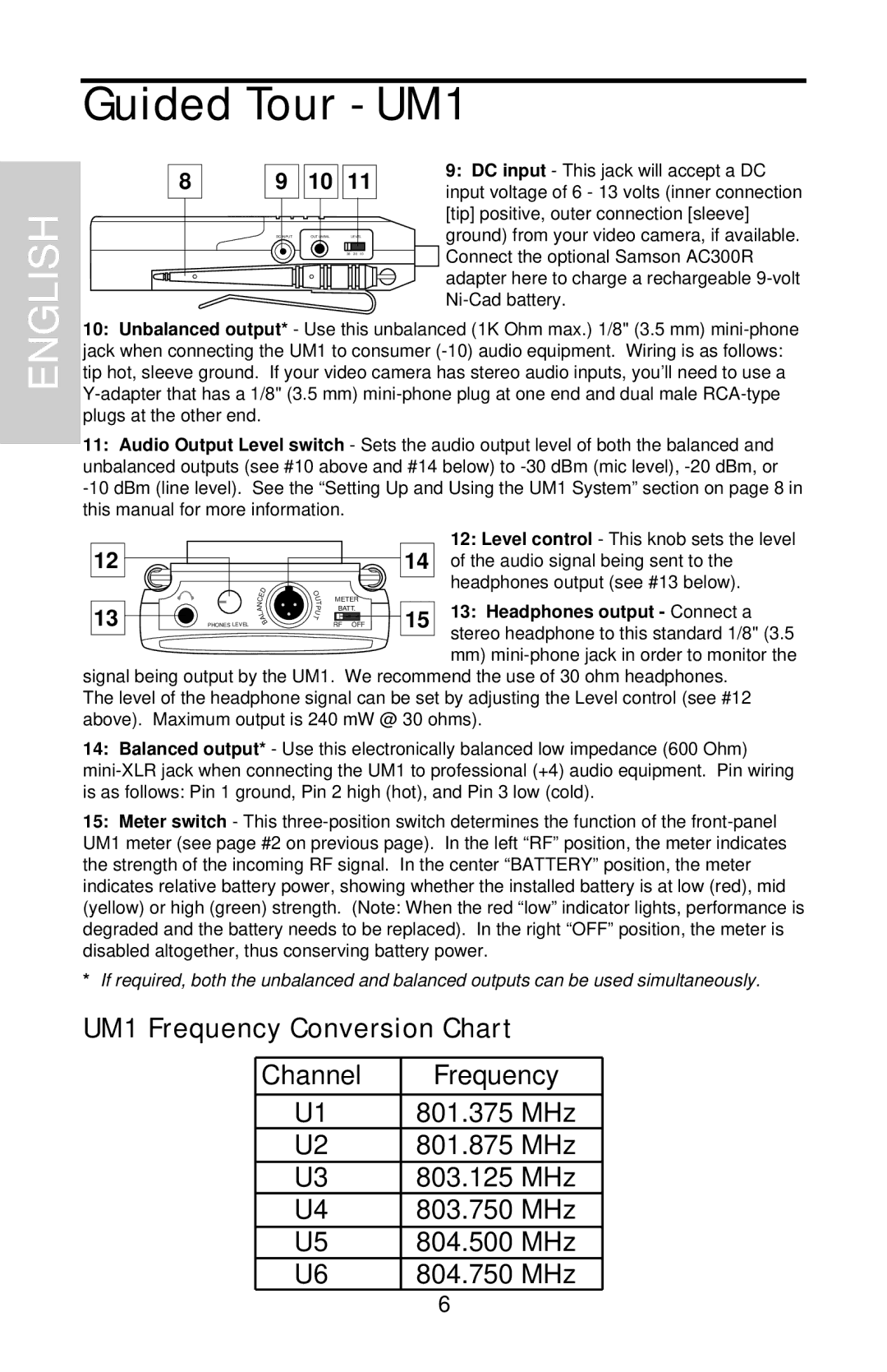
9:DC input - This jack will accept a DC input voltage of 6 - 13 volts (inner connection [tip] positive, outer connection [sleeve] ground) from your video camera, if available. Connect the optional Samson AC300R adapter here to charge a rechargeable
10:Unbalanced output* - Use this unbalanced (1K Ohm max.) 1/8" (3.5 mm)
11:Audio Output Level switch - Sets the audio output level of both the balanced and unbalanced outputs (see #10 above and #14 below) to
12 |
|
|
|
|
|
| 12: Level control - This knob sets the level |
|
|
|
|
| 14 of the audio signal being sent to the | ||
|
| E | D | O |
|
| headphones output (see #13 below). |
|
|
| U | METER |
|
| |
|
| C |
| T |
|
| |
|
| N |
| BATT. |
| 13: Headphones output - Connect a | |
13 |
| A | P | 15 | |||
| L | U |
| ||||
| A | T |
| ||||
PHONES LEVEL |
| B | RF OFF | ||||
|
|
|
|
|
|
| stereo headphone to this standard 1/8" (3.5 |
|
|
|
|
|
|
| mm) |
signal being output by the UM1. We recommend the use of 30 ohm headphones. The level of the headphone signal can be set by adjusting the Level control (see #12 above). Maximum output is 240 mW @ 30 ohms).
14:Balanced output* - Use this electronically balanced low impedance (600 Ohm)
15:Meter switch - This
*If required, both the unbalanced and balanced outputs can be used simultaneously.
UM1 Frequency Conversion Chart
Channel | Frequency |
|
|
U1 | 801.375 MHz |
U2 | 801.875 MHz |
U3 | 803.125 MHz |
U4 | 803.750 MHz |
U5 | 804.500 MHz |
U6 | 804.750 MHz |
6