Connecting the assembly cable
1. Extend the assembly cable if necessary.
• Do not connect two or more different cables to extend the length. It may cause fire.
2 . Open the cover panel.
3 . Remove the screw securing the connector cover.
4 . Pass the assembly cable through the rear of the indoor unit and connect the assembly cable to terminals. (Refer to the picture below)
• Each wire is labeled with the corresponding terminal number.
5 . Pass the other end of the cable through the 65 mm hole in the wall.
6 . Close the connector cover by tightening the screw carefully.
7 . Close the cover panel.
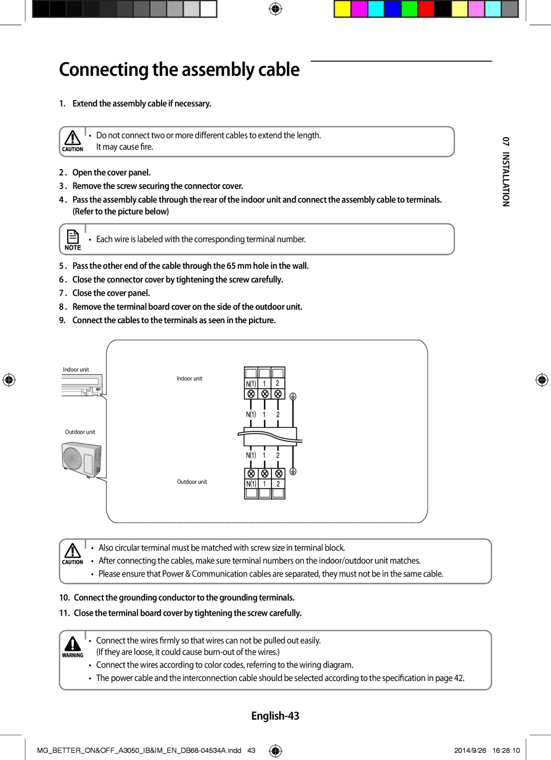
8 . Remove the terminal board cover on the side of the outdoor unit. 9. Connect the cables to the terminals as seen in the picture.
Indoor unit
Indoor unit
Outdoor unit
Outdoor unit
• Also circular terminal must be matched with screw size in terminal block.
• After connecting the cables, make sure terminal numbers on the indoor/outdoor unit matches.
•Please ensure that Power & Communication cables are separated, they must not be in the same cable.
10.Connect the grounding conductor to the grounding terminals.
11.Close the terminal board cover by tightening the screw carefully.
•Connect the wires firmly so that wires can not be pulled out easily.
(If they are loose, it could cause
•Connect the wires according to color codes, referring to the wiring diagram.
•The power cable and the interconnection cable should be selected according to the specification in page 42.
English-43
07 INSTALLATION
2014/9/26 16:28:10