1. Extend the assembly cable if necessary.
• Do not connect two or more different cables to extend the length. It may cause fire.
2 . Open the front grille.
3 . Remove the screw securing the connector cover.
4 . Pass the assembly cable through the rear of the indoor unit and connect the assembly cable to terminals. (Refer to the picture below)
• Each wire is labeled with the corresponding terminal number.
5 . Pass the other end of the cable through the 65mm hole in the wall.
6 . Close the connector cover by tightening the screw carefully.
7 . Close the front grille.
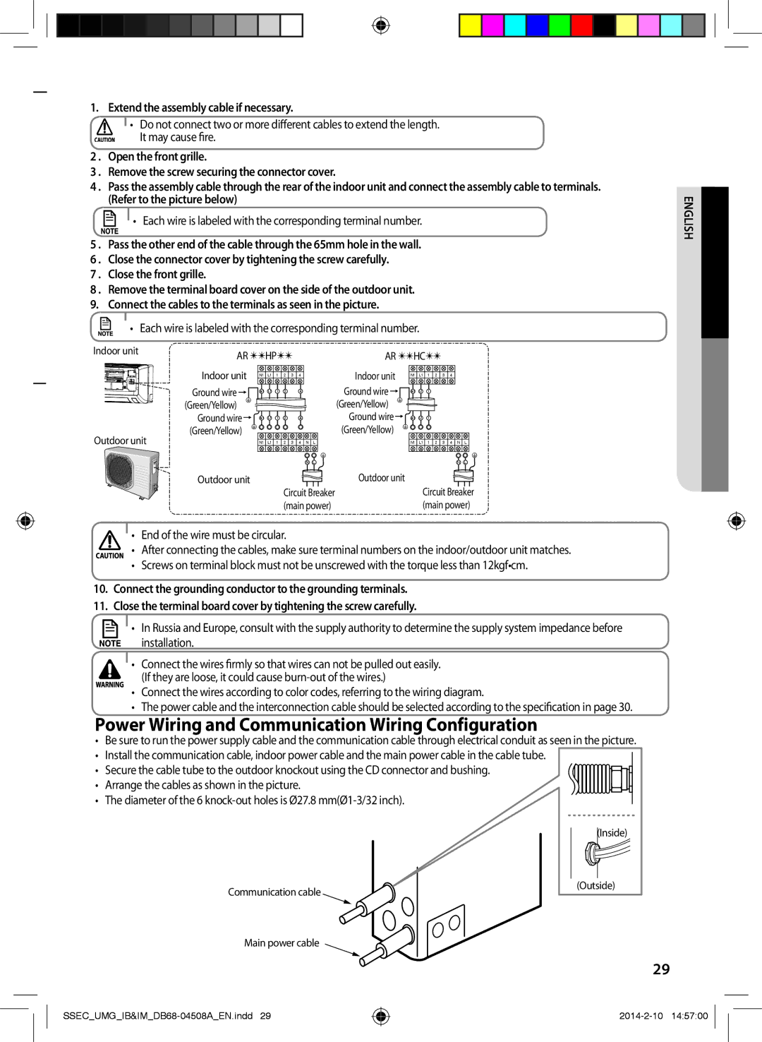
8 . Remove the terminal board cover on the side of the outdoor unit. 9. Connect the cables to the terminals as seen in the picture.
• Each wire is labeled with the corresponding terminal number.
Indoor unit | AR HP |
|
| AR HC |
|
|
| |||||||||
|
|
|
|
|
| |||||||||||
| Indoor unit | N1 | L1 | 1 | 2 | 3 | 4 |
| Indoor unit | N1 | L1 | 1 | 2 | 3 | 4 |
|
| Ground wire | N1 | L1 | 1 | 2 |
| 4 |
| Ground wire | N1 | L1 | 1 |
|
|
|
|
| (Green/Yellow) |
|
|
|
|
|
|
| (Green/Yellow) |
|
|
|
|
|
|
|
| Ground wire | N1 | L1 | 1 | 2 |
| 4 |
| Ground wire | N1 | L1 | 1 |
|
|
|
|
Outdoor unit | (Green/Yellow) |
|
|
|
|
|
|
| (Green/Yellow) |
|
|
|
|
|
|
|
| N1 | L1 | 1 | 2 | 3 | 4 N | L |
| N1 | L1 | 1 | 2 | 3 | 4 N | L | |
|
|
|
|
|
|
| N | L |
|
|
|
|
|
| N | L |
| Outdoor unit |
|
|
| Circuit Breaker | Outdoor unit |
| Circuit Breaker | ||||||||
|
|
|
|
|
|
| ||||||||||
|
|
|
|
| (main power) |
|
| (main power) | ||||||||
• End of the wire must be circular.
• After connecting the cables, make sure terminal numbers on the indoor/outdoor unit matches.
• Screws on terminal block must not be unscrewed with the torque less than 12kgf•cm.
10. Connect the grounding conductor to the grounding terminals.
11. Close the terminal board cover by tightening the screw carefully.
• In Russia and Europe, consult with the supply authority to determine the supply system impedance before
installation.
• Connect the wires firmly so that wires can not be pulled out easily. (If they are loose, it could cause
• Connect the wires according to color codes, referring to the wiring diagram.
• The power cable and the interconnection cable should be selected according to the specification in page 30.
Power Wiring and Communication Wiring Configuration
• Be sure to run the power supply cable and the communication cable through electrical conduit as seen in the picture.
• Install the communication cable, indoor power cable and the main power cable in the cable tube.
• Secure the cable tube to the outdoor knockout using the CD connector and bushing.
• Arrange the cables as shown in the picture.
• The diameter of the 6
ENGLISH
Communication cable
Main power cable
(Inside)
(Outside)
29