Network Camera
Overview
English
Overview
FCC Statement
Important Safety Instructions
Contents
Connecting to the camera
Login
Installing ActiveX
Using the Live Screen
Product Features
Recommended PC Specifications
Compatible PoE Switches
Compatible IP Routers
IP Installer CD
WHAT’S Included
Lens Options
CS Lens
Connector
AT a Glance
Front Side
Description
Power
Rear Side
System
GND
Disconnect the power before proceeding
Mounting the Lens
Mounting the CS lens
Mounting the C lens
Connecting the Auto Iris Lens connector
Focusing
Connecting with Other Device
Connecting to the monitor
Power Supply
Network Connection
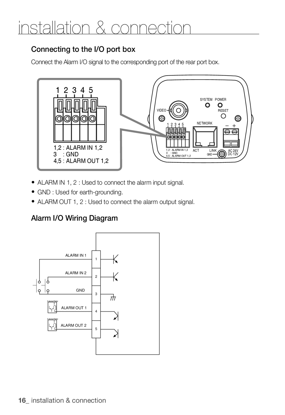
Connecting to the I/O port box
Alarm I/O Wiring Diagram
HOW to USE the Keyboard Controller
You can configure the camera settings using the Web Viewer
Main Menu
Factory Defaults
Profile
Camera ID
Camera Setup
Iris
Motion
DNR
Shutter
SENS-UP
You can specify a recording mode according to the scene
DAY/NIGHT
White BAL
Select Camera SET DAY/NIGHT
Digital Zoom
Detail
AGC Color SUP
Reverse
Zone Setup
Privacy Zone
Factory Default
Others
OSD Color
You can set the font color of the user interface
The camera type may different, depend on the video signal
System Info
Language
You can check the system information
Network connection and setup
Network Connection and Setup
Setting the IP Router
Connecting the Camera Directly to Local Area Networking
Connecting to the camera from a local PC in the LAN
IP Address Setup
Buttons used in IP Installer
Static IP Setup
Manual Network Setup
URL
Ddns registration has failed
Network connection and setup
Auto Network Setup
Dynamic IP Setup
Dynamic IP Environment Setup
Connecting to the Camera from a Shared Local PC
Port Range Forward Port Mapping Setup
Manual Port Range Forwarding
Connecting to the Camera from a Remote PC VIA the Internet
Connecting to the Camera
Using URL
Connecting via URL If the Http port is other than
Normally, you would
Login
To check the Ddns address
Installing Activex
For Windows XP Service Pack 2 users
Click Install ActiveX Control
Security warning popup appears, click Install
Using the Live Screen
To capture the snapshot
Backup
To print out the screenshot
Click on the scene to record
To record a video
Recorded space, recording will be forcibly ended Click OK
Accessing the Setup Screen
Setup screen appears
To configure the video settings
Default Setup
Contrast Adjust the contrast from
To configure the IP settings
Click Basic User User setup window appears
To set the user account
English
System Setup
When done, click Apply Selected language will be applied
To set the display language
To set the date/time
To check the log information
To update the software
Select System Log Log information list appears
To reset the system
To set the Https
To set the text
Overlay Setup
You can display text on the screen
To set the event transfer function
Event Setup
Verified will be displayed
English
To set an alarm image
FTP transfer The image is sent to the specifi ed FTP address
Select Event Motion Motion Detection setup window appears
To set the alarm input
To set the motion detection function
To set a motion area
Motion Detection function will operate on the selected area
To set the video transfer mode
Network Setup
To set the scheduled transfer
To set the Ddns
DAY Mode
ITS
Gaming
ALC
Cavlc
Terminology
Bitrate Control CBRConstant Bitrate
Specifications
CS/C
RAM
DSP
4CIF
Setup
Ntsc
HTTPS, SSL, Dhcp
ARP, DNS, DDNS, Vsip
Power
PoE Power over Ethernet
~90% Dimension W72 X D139 X H60 Weight About 300g
About 7W
EstimationHPel
Frame Rate Ntsc
GOP size15 MPEG4 4CIF
30 FPS 15 FPS
FPS
MPEG4 VGA
264 VGA
MPEG4 CIF
264 CIF
Frame Rate PAL
25 FPS 13 FPS
MPEG4 VGA
Kbps 17 FPS
MPEG4 CIF
264 CIF
Troubleshooting
Problem Solution
Verify the settings in the following sequence
NTP must be properly configured
Motion Detection Feature must be enabled
Alarm Video Transmission must be enabled
GPL/LGPL Software License
GNU General Public License
Preamble
We protect your rights with two steps
Program, and can be reasonably
Page
Page
How to Apply These Terms to Your New Programs
No Warranty
END of Terms and Conditions
Preamble
Terms and Conditions
Basic Permissions
Source Code
Protecting Users Legal Rights From Anti-Circumvention Law
Conveying Modified Source Versions
Conveying Verbatim Copies
Conveying Non-Source Forms
Installed in ROM
Additional Terms
Automatic Licensing of Downstream Recipients
Acceptance Not Required for Having Copies
Patents
No Surrender of Others Freedom
Valid
Use with the GNU Affero General Public License
GNU Lesser General Public License
END of Terms and Conditions
Preamble
Page
Page
AAccompany the work with the complete corresponding machine
Page
Page
How to Apply These Terms to Your New Libraries
OpenSSL License
No Event Shall the OpenSSL
Copyright C1995-1998 Eric Young
Original SSLeay License
And/or other materials provided with the distribution