VMAA26 specifications
The Sanus Systems VMAA26 is a premium television mount designed to enhance your viewing experience while providing a sleek and stylish look for your home entertainment setup. This versatile TV mount accommodates various TV sizes ranging from 32 to 70 inches, making it an excellent choice for almost any modern television. With a weight capacity of up to 130 pounds, the VMAA26 ensures stability and security for your valuable equipment, giving you peace of mind during use.One of the standout features of the VMAA26 is its full-motion capability, which allows for tilting, swiveling, and extending the television from the wall. This enhances viewing angles, allowing you to enjoy your favorite shows and movies from different positions in the room. The mount supports a tilt range of up to 12 degrees, reducing glare and improving comfort, particularly in bright rooms. With swivel capabilities of up to 180 degrees, you can easily adjust the screen direction to achieve an optimal viewing angle.
Additionally, the Sanus VMAA26 incorporates a low-profile design, ensuring that your TV sits close to the wall when not in use. This feature not only saves space but also adds an aesthetically pleasing touch to your living area. The mount is made from high-quality, durable materials, providing long-lasting performance and a secure hold for your TV. Its robust construction is designed to withstand the rigors of everyday use.
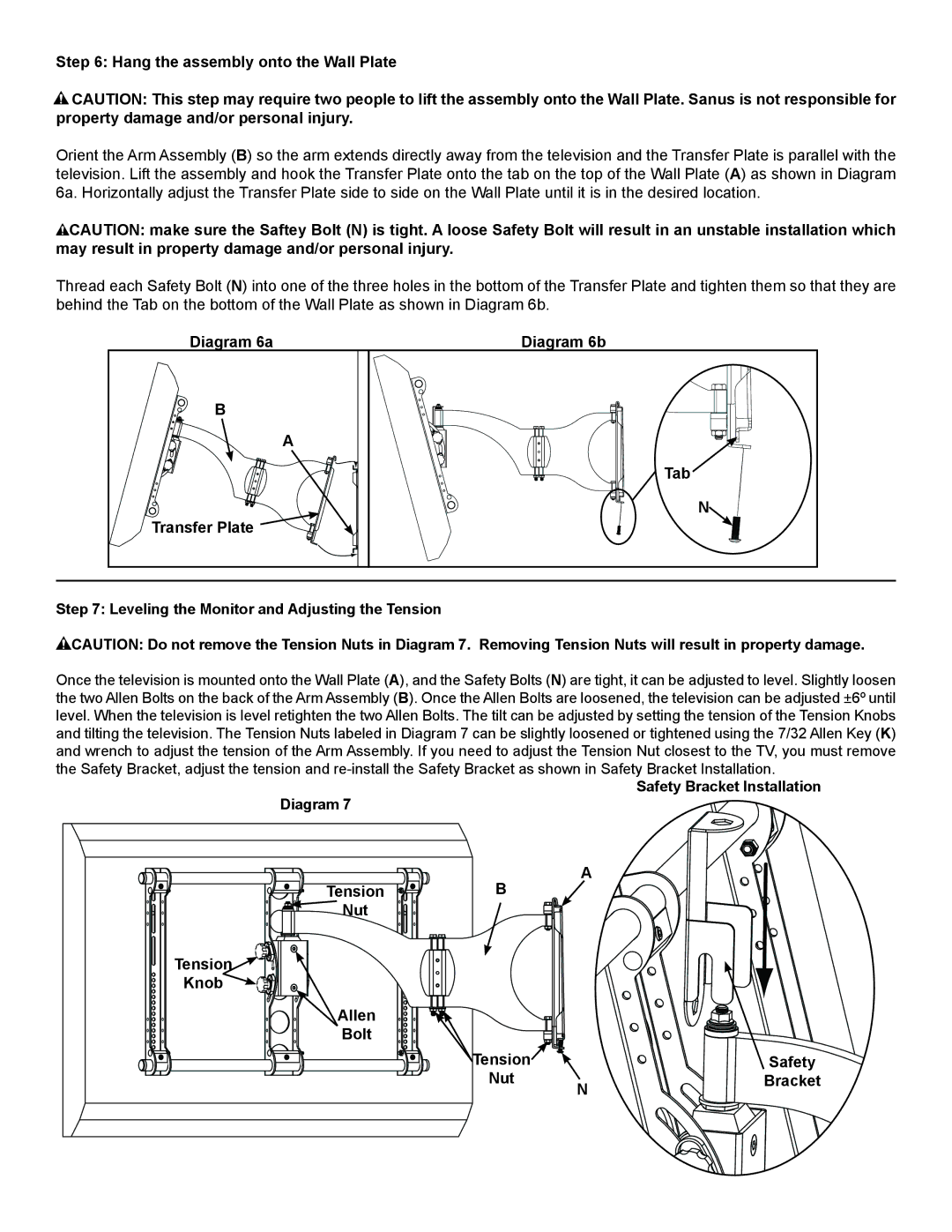
Installation of the VMAA26 is straightforward, thanks to its user-friendly instructions and included hardware. The mount features simple, straightforward steps, and the installation template makes aligning your TV effortless. This attention to detail ensures that even those with limited DIY experience can successfully mount their TV with confidence.
Another significant technology integrated into this mount is its cable management system, which helps eliminate clutter by concealing cables and wires. This feature not only keeps your entertainment area looking neat and organized, but it also enhances safety by preventing tripping hazards.
In summary, the Sanus Systems VMAA26 offers a combination of functionality, style, and practicality. Its full-motion capabilities, low-profile design, ease of installation, and effective cable management make it an exceptional choice for anyone looking to elevate their home entertainment experience. Whether you're a movie enthusiast or a casual viewer, the VMAA26 ensures you can enjoy your TV in comfort and style.

