INSTALLATION INSTRUCTIONS
How to Attach the “ Magic ” Hose Joint
1.Loosen the four screws and slide the top of the "Magic"Hose Joint(section A in the figure)onto the faucet. Then, securely tighten the four screws provided with the “Magic" Hose Joint by using a screwdriver to secure the top of the joint to the faucet.
2.Remove the CAUTION label from the "Magic" Hose Joint.
3.Turn the male coupler on the joint (section B in the figure) clockwise to attach it securely
to the top of the joint (section A in the figure). |
INSTALLATION INSTRUCTIONS
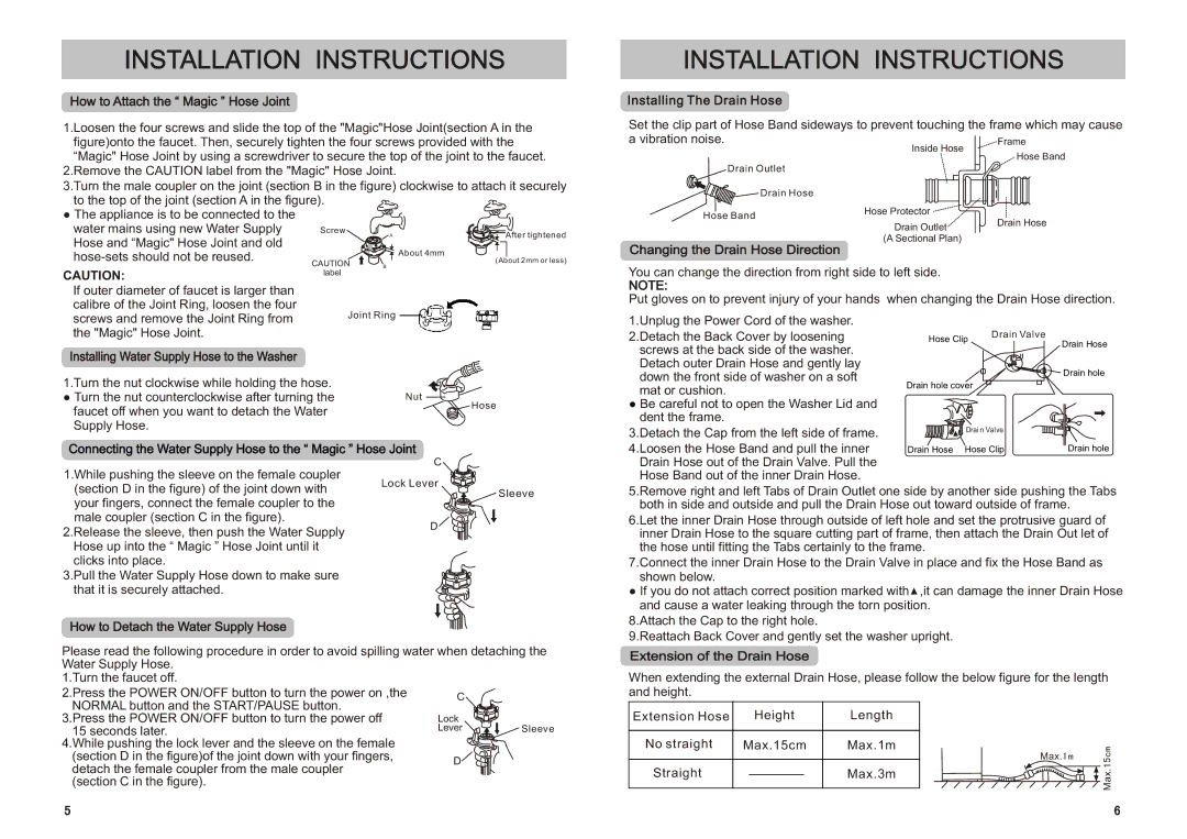
Installing The Drain Hose
Set the clip part of Hose Band sideways to prevent touching the frame which may cause a vibration noise.
Inside Hose
Drain Outlet
![]()
![]()
![]() Drain Hose
Drain Hose
● The appliance is to be connected to the |
|
|
water mains using new Water Supply | Screw | After tightened |
Hose and “Magic" Hose Joint and old | A | |
|
|
Hose Band
Hose Protector
Drain Outlet
(A Sectional Plan)
About 4mm | |
(About 2mm or less) | |
CAUTION | B |
CAUTION:label
If outer diameter of faucet is larger than
calibre of the Joint Ring, loosen the four
screws and remove the Joint Ring from Joint Ring the "Magic" Hose Joint.
Installing Water Supply Hose to the Washer
1.Turn the nut clockwise while holding the hose. |
| |
● Turn the nut counterclockwise after turning the | Nut | |
faucet off when you want to detach the Water | Hose | |
| ||
Supply Hose. |
| |
Connecting the Water Supply Hose to the “ Magic ” Hose Joint | ||
1.While pushing the sleeve on the female coupler | C | |
Lock Lever | ||
(section D in the figure) of the joint down with | ||
Sleeve | ||
your fingers, connect the female coupler to the |
| |
male coupler (section C in the figure). | D | |
2.Release the sleeve, then push the Water Supply | ||
| ||
Hose up into the “ Magic ” Hose Joint until it |
| |
clicks into place. |
| |
3.Pull the Water Supply Hose down to make sure |
| |
that it is securely attached. |
| |
How to Detach the Water Supply Hose
Please read the following procedure in order to avoid spilling water when detaching the Water Supply Hose.
1.Turn the faucet off. |
|
2.Press the POWER ON/OFF button to turn the power on ,the | C |
Changing the Drain Hose Direction
You can change the direction from right side to left side.
NOTE:
Put gloves on to prevent injury of your hands
1.Unplug the Power Cord of the washer. 2.Detach the Back Cover by loosening screws at the back side of the washer.
Detach outer Drain Hose and gently lay down the front side of washer on a soft mat or cushion.
● Be careful not to open the Washer Lid and dent the frame.
3.Detach the Cap from the left side of frame. 4.Loosen the Hose Band and pull the inner Drain Hose out of the Drain Valve. Pull the Hose Band out of the inner Drain Hose.
5.Remove right and left Tabs of Drain Outlet one side by another side pushing the Tabs both in side and outside and pull the Drain Hose out toward outside of frame.
6.Let the inner Drain Hose through outside of left hole and set the protrusive guard of inner Drain Hose to the square cutting part of frame, then attach the Drain Out let of the hose until fitting the Tabs certainly to the frame.
7.Connect the inner Drain Hose to the Drain Valve in place and fix the Hose Band as shown below.
●If you do not attach correct position marked with![]() ,it can damage the inner Drain Hose and cause a water leaking through the torn position.
,it can damage the inner Drain Hose and cause a water leaking through the torn position.
8.Attach the Cap to the right hole.
9.Reattach Back Cover and gently set the washer upright.
Extension of the Drain Hose
When extending the external Drain Hose, please follow the below figure for the length and height.
NORMAL button and the START/PAUSE button. |
|
|
3.Press the POWER ON/OFF button to turn the power off | Lock |
|
15 seconds later. | Lever | Sleeve |
4.While pushing the lock lever and the sleeve on the female |
|
|
(section D in the figure)of the joint down with your fingers, | D |
|
detach the female coupler from the male coupler |
| |
|
| |
(section C in the figure). |
|
|
Extension Hose |
| Height | Length | |
|
|
|
|
|
No straight | Max.15cm | Max.1m | ||
|
|
|
|
|
Straight |
|
|
| Max.3m |
|
|
| ||
|
|
|
|
|
Max.1m
Max.15cm
5 | 6 |