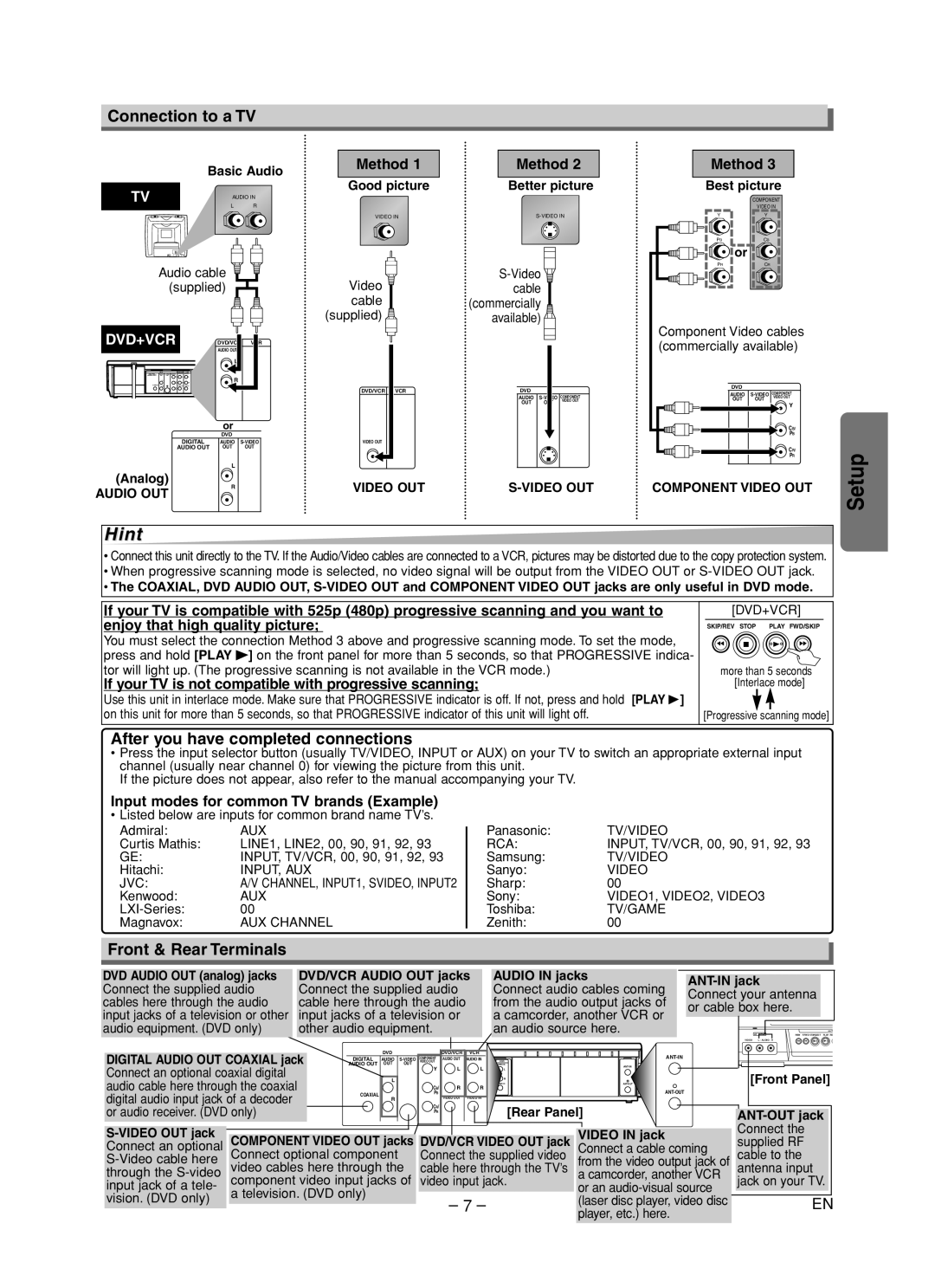
Connection to a TV
Basic Audio
TV | AUDIO IN |
| L R |
Audio cable ![]()
![]() (supplied)
(supplied) ![]()
DVD+VCR | DVD/VCR | VCR |
| AUDIO OUT |
|
| L |
|
| R |
|
| or |
|
| DVD |
|
DIGITAL | AUDIO | COMPONENT | |
VIDEO OUT | |||
AUDIO OUT | OUT | OUT | Y |
|
|
| |
(Analog) | L |
|
|
|
| PB | |
|
|
| CB/ |
AUDIO OUT | R |
|
|
|
| CR/ | |
|
|
| PR |
Method 1 | Method 2 |
Good picture | Better picture |
VIDEO IN |
Video |
|
| |||
|
| cable |
| ||
cable |
| (commercially |
| ||
(supplied) |
| available) |
| ||
DVD/VCR | VCR |
| DVD |
|
|
|
| DIGITAL | AUDIO | COMPONENT | |
|
| VIDEO OUT | |||
|
| AUDIO OUT | OUT | OUT |
|
VIDEO OUT |
| COAXIAL |
|
| |
|
|
|
|
| |
VIDEO OUT |
Method 3
Best picture
COMPONENT
VIDEO IN
YY
PBCB
or
PRCR
Component Video cables (commercially available)
| DVD |
|
|
DIGITAL | AUDIO | COMPONENT | |
VIDEO OUT | |||
AUDIO OUT | OUT | OUT | Y |
|
|
| |
|
|
| CB/ |
COAXIAL |
|
| PB |
|
|
| CR/ |
|
|
| PR |
COMPONENT VIDEO OUT
Setup
Hint
•Connect this unit directly to the TV. If the Audio/Video cables are connected to a VCR, pictures may be distorted due to the copy protection system.
•When progressive scanning mode is selected, no video signal will be output from the VIDEO OUT or
•The COAXIAL, DVD AUDIO OUT,
If your TV is compatible with 525p (480p) progressive scanning and you want to enjoy that high quality picture;
You must select the connection Method 3 above and progressive scanning mode. To set the mode, press and hold [PLAY B] on the front panel for more than 5 seconds, so that PROGRESSIVE indica- tor will light up. (The progressive scanning is not available in the VCR mode.)
If your TV is not compatible with progressive scanning;
Use this unit in interlace mode. Make sure that PROGRESSIVE indicator is off. If not, press and hold [PLAY B] on this unit for more than 5 seconds, so that PROGRESSIVE indicator of this unit will light off.
[DVD+VCR]
SKIP/REV STOP | PLAY FWD/SKIP |
E C B D
more than 5 seconds [Interlace mode]
[Progressive scanning mode]
After you have completed connections
•Press the input selector button (usually TV/VIDEO, INPUT or AUX) on your TV to switch an appropriate external input channel (usually near channel 0) for viewing the picture from this unit.
If the picture does not appear, also refer to the manual accompanying your TV.
Input modes for common TV brands (Example)
•Listed below are inputs for common brand name TV’s.
Admiral: | AUX |
Curtis Mathis: | LINE1, LINE2, 00, 90, 91, 92, 93 |
GE: | INPUT, TV/VCR, 00, 90, 91, 92, 93 |
Hitachi: | INPUT, AUX |
JVC: | A/V CHANNEL, INPUT1, SVIDEO, INPUT2 |
Kenwood: | AUX |
00 | |
Magnavox: | AUX CHANNEL |
Panasonic: | TV/VIDEO |
RCA: | INPUT, TV/VCR, 00, 90, 91, 92, 93 |
Samsung: | TV/VIDEO |
Sanyo: | VIDEO |
Sharp: | 00 |
Sony: | VIDEO1, VIDEO2, VIDEO3 |
Toshiba: | TV/GAME |
Zenith: | 00 |
Front & Rear Terminals |
|
|
|
|
|
|
|
|
|
|
|
|
|
|
| ||
DVD AUDIO OUT (analog) jacks | DVD/VCR AUDIO OUT jacks | AUDIO IN jacks |
|
|
| ||||||||||||
Connect the supplied audio | Connect the supplied audio |
| Connect audio cables coming |
|
| ||||||||||||
| Connect your antenna | ||||||||||||||||
cables here through the audio | cable here through the audio | from the audio output jacks of | |||||||||||||||
or cable box here. |
|
| |||||||||||||||
input jacks of a television or other | input jacks of a television or |
| a camcorder, another VCR or |
|
| ||||||||||||
|
|
|
|
| |||||||||||||
audio equipment. (DVD only) | other audio equipment. |
|
|
| an audio source here. |
| AV INPUT | REW | F.FWD STOP/EJECT PLAY RE | ||||||||
|
|
|
|
|
|
|
|
|
|
|
|
|
|
|
| R | |
|
|
|
|
|
|
|
|
|
|
|
|
|
| VIDEO L - AUDIO - R | E | D CA B | |
DIGITAL AUDIO OUT COAXIAL jack | AUDIO OUT | DVD | OUT |
| DVD/VCR | VCR |
|
|
|
|
|
|
| ||||
OUT |
| AUDIO OUT | OUT | OUT VIDEO OUT |
|
|
|
|
|
| |||||||
|
|
| DIGITAL | AUDIO | COMPONENT | AUDIO OUT | AUDIO IN |
|
|
|
|
|
| ||||
|
|
| VIDEO OUT | DIGITAL | DVD | DVD/VCR | VCR |
|
|
|
|
| |||||
Connect an optional coaxial digital |
|
|
|
|
| AUDIO | AUDIO OUT | AUDIO IN |
|
|
|
|
| ||||
|
|
|
| Y |
| L | LY | L | L |
|
| [Front Panel] | |||||
|
|
|
|
|
| L | PCBB/ | R | R |
|
| ||||||
audio cable here through the coaxial |
|
| L |
|
| COAXIAL | R | RPCRR/ | VIDEO OUT | VIDEO IN |
| ||||||
|
|
|
| CB/ | R |
|
|
|
|
|
| ||||||
digital audio input jack of a decoder |
| COAXIAL |
|
| PB |
|
|
|
|
|
|
|
| ||||
| R |
|
| VIDEO OUT | VIDEO IN |
|
|
|
|
|
|
| |||||
|
|
|
|
|
|
|
|
|
|
| |||||||
or audio receiver. (DVD only) |
|
|
|
| CR/ |
|
|
| [Rear Panel] |
| |||||||
|
|
|
| PR |
|
|
|
| |||||||||
COMPONENT VIDEO OUT jacks DVD/VCR VIDEO OUT jack | VIDEO IN jack |
| Connect the | ||||||||||||||
| supplied RF | ||||||||||||||||
Connect an optional | Connect a cable coming | ||||||||||||||||
Connect optional component |
| Connect the supplied video | from the video output jack of | cable to the |
| ||||||||||||
through the | video cables here through the | cable here through the TV’s | a camcorder, another VCR | antenna input | |||||||||||||
input jack of a tele- | component video input jacks of | video input jack. | or an | jack on your TV. | |||||||||||||
a television. (DVD only) |
|
|
|
|
|
|
|
|
|
|
| ||||||
vision. (DVD only) |
|
|
| – 7 – |
|
| (laser disc player, video disc |
|
| EN | |||||||
|
|
|
|
|
|
|
|
|
| ||||||||
|
|
|
|
|
|
|
|
| player, etc.) here. |
|
|
| |||||
|
|
|
|
|
|
|
|
|
|
|
|
|
|
|
| ||