Manuals
/
Sanyo
/
Household Appliance
/
Air Conditioner
Sanyo
KMS2472, KMS1872
service manual
Dimensional Data, KMS0972 KMS1272
Models:
KMS1872
KMS2472
1
22
85
85
Download
85 pages
54.08 Kb
19
20
21
22
23
24
25
26
Troubleshooting
Specs
Install
Refrigerant Flow Diagram
Timer backup
Loose wiring may cause
Dimension
Method of Self-Diagnostics
Setting procedure
Setting the airflow manually
Page 22
Image 22
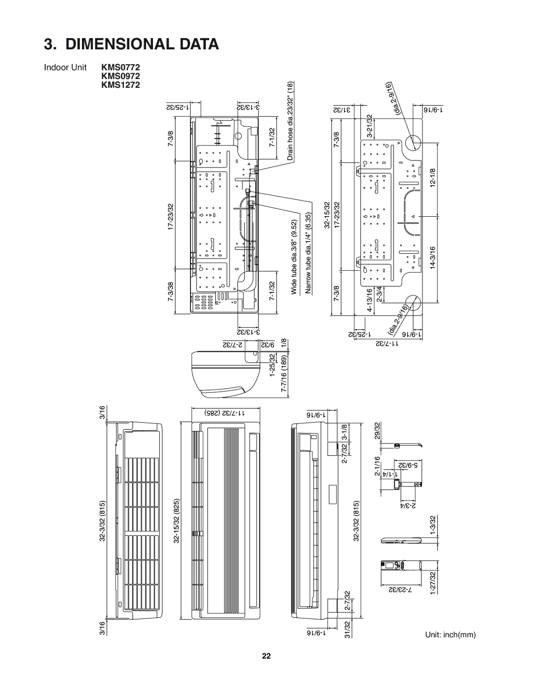
3. DIMENSIONAL DATA
Indoor Unit
KMS0772
KMS0972
KMS1272
Unit: inch(mm)
22
Page 21
Page 23
Page 22
Image 22
Page 21
Page 23
Contents
11,900BTU / h KMS1272
Capacity Indoor Model No Product Code No 500BTU / h KMS0772
000BTU / h KMS0972
17,500BTU / h KMS1872
Please Read Before Starting
Table of Contents
Applicable MULTI-OUTDOOR Units
Temperature Indoor Air Intake Temp Outdoor Air Intake Temp
Indoor Air Intake Temp Outdoor Air Intake Temp
Unit Specifications
KMS0772
208V
KMS0972
KMS0972
KMS1272
KMS1272
KMS1872
KMS1872
KMS2472
KMS2472
Major Component Specifications
Indoor Unit
CB-KMS0972
CB-KMS1272
CB-KMS1872
CB-KMS2472
Temperature F C
Other Component Specifications
Resistance k ohm
Dimensional Data
KMS0972 KMS1272
Indoor Unit KMS1872 KMS2472
Refrigerant Flow Diagram
Indoor Unit KMS0772 KMS0972 KMS1272 Indoor unit
Air Throw Distance Charts
Performance Data
Indoor Unit
Indoor Unit
Indoor Unit
Indoor Unit
Electric Wiring Diagrams
Indoor Unit KMS0772 KMS0972 KMS1272
8FA2-5257-70500-0
Emergency operation
Operation Functions
PAM- control
Timer backup
Lamp colors
Protective Functions
Freeze prevention
Precautions before Performing Inspection or Repair
Method of Self-Diagnostics
Indication on indoor unit
Self-diagnostics Lamps
Code Diagnostics item
Blinking On Illuminated
Replace the controller
Replace the circuit board or the fuse
Checking the indoor unit Control Check items unit operation
Using the TEST/T-RUN terminals
Checking the Indoor and Outdoor Units
Checking the serial communications
Trouble Diagnosis of Fan Motor
Indoor Fan Motor
Electromagnetic interference
Noise Malfunction and Electromagnetic Interference
Noise malfunction
Locations most susceptible to noise Trouble Correction
KMS0772 KMS0972 KMS1272 KMS1872 KMS2472
Features
Alert Symbols
Contents
Product Information
Safety Instructions
Installation Location
Electrical Requirements
Names of Parts
Unit Display and Operation Button
Quiet lamp
Remote Control Unit Display
Advance button
Remote Control Unit
HR. Timer button
Transmitter
DRY
Temperature Display Selector button
Using the Remote Control Unit
How to Install Batteries
ACL button ALL Clear
Using the Remote Control Unit
Operation with the Remote Control Unit
Operation
Operation with the Remote Control Unit
Press the ON/OFF operation button
Cooling and DRY Mode
Night Setback Mode is used for saving energy
Quiet Mode
Special Remarks
Power failure during operation
Clicking sound is heard from the air conditioner
Setting the Timer
Operation Indication
To cancel a timer program Press the Cancel button
Setting the Timer
1030 pm 710 am 1100 am Present time
Cancellation procedure
Using the 1-Hour OFF Timer
Setting procedure
Operation together with the Daily ON/OFF Repeat Timer
Horizontal
Adjusting the Airflow Direction
Setting the airflow manually
Sweep function
Operation without the Remote
Care and Cleaning
When the air conditioner is not running
Control Unit
How to replace the anti-mold filter
Care and Cleaning
How to remove the anti-mold filter
Air intake grille
Cleaning the negative ion generator
How to clean the air clean filter
How to install the air clean filter
Washing the grille with water
Operating Range
Troubleshooting
Trouble Possible Cause Remedy
Appendix B Installation Instructions
Contents
For Indoor Unit
…In a Ceiling or Wall
For safe installation and trouble-free operation, you must
Please Read Before Starting
…In a Room
General
Installation Site Selection
Additional Materials Required for Installation
Embedding the Tubing and Wiring
150 L1+L2+L3+L4 230
Remove the Rear Panel from the Unit
How to Install the Indoor Unit
Make a Hole
If Wooden Wall
Install the Rear Panel on the Wall
If Block, Brick, Concrete or Similar Type Wall
Be sure to wear work gloves
How to remove the grille
How to replace the grille
Cut by the sharp aluminum fins
Indoor unit types KMS1872, KMS2472
Wiring Instructions General precautions on wiring
Shape the Indoor Side Tubing
Wiring Instructions for Inter-unit Connections
How to connect wiring to the terminal For Indoor Unit
Loose wiring may cause
Fore, be sure all wiring is
For Outdoor Unit For solid core wiring or F-cable
Mounting
Right-side tubing
Left-side tubing
Switching drain hose and drain cap
Drain cap
To unmount indoor unit
Risk of Electric Shock
How to Test Run the Air Conditioner
Operation lamp Timer lamp Quiet lamp ION lamp
Remote Control Unit Installation Position
Mounting on a Wall
Address Switch
Address Setting of the Remote Control Unit
Connecting a Home Automation device
Installation Check Sheet
Top
Page
Image
Contents