APPENDIX
CONFIGURATIONS OF TERMINALS
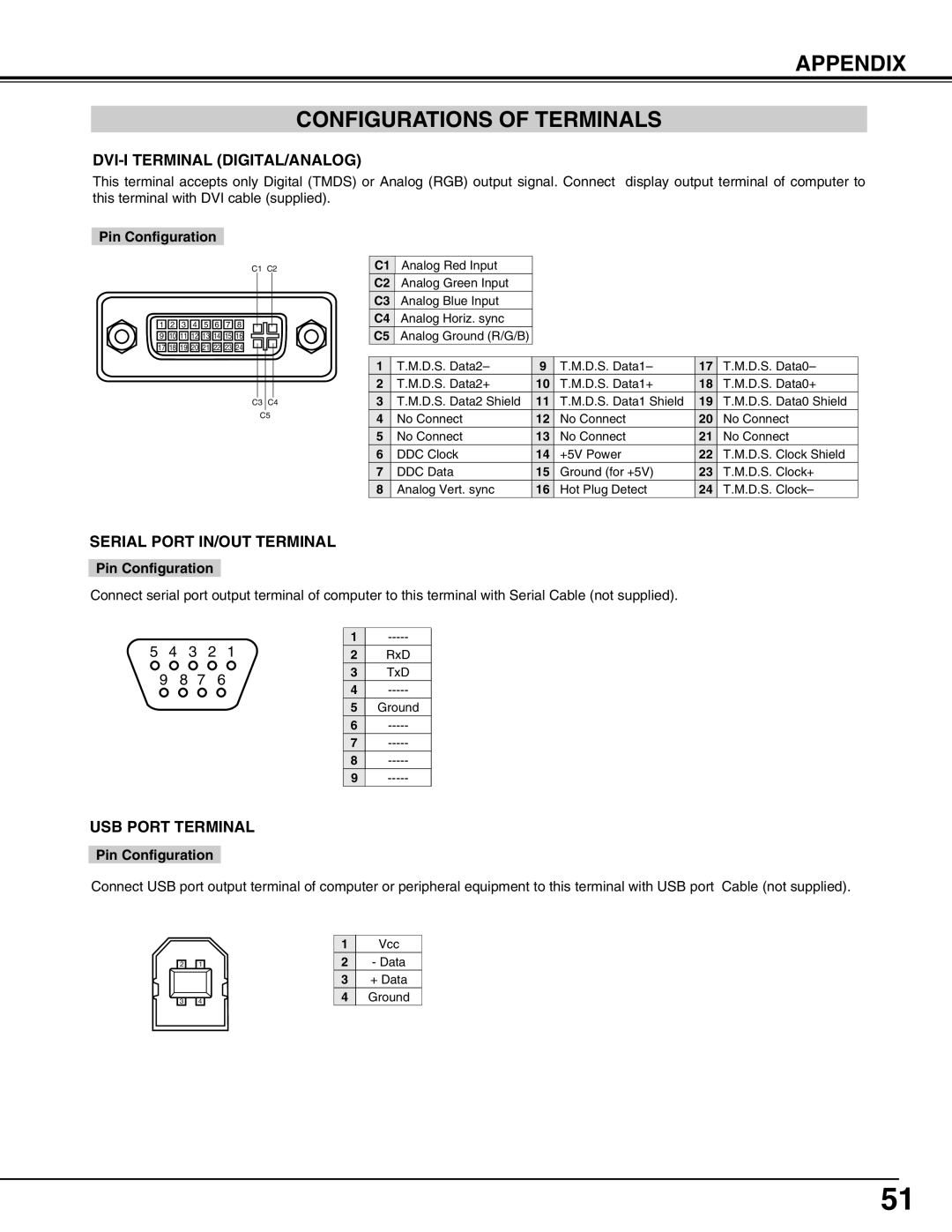
This terminal accepts only Digital (TMDS) or Analog (RGB) output signal. Connect display output terminal of computer to this terminal with DVI cable (supplied).
Pin Configuration
C1 C2
![]() 1
1 ![]()
![]() 2
2 ![]()
![]() 3
3 ![]()
![]() 4
4 ![]()
![]() 5
5 ![]()
![]() 6
6 ![]()
![]() 7
7 ![]()
![]() 8
8 ![]()
![]() 9
9 ![]()
![]() 10
10![]()
![]() 11
11![]()
![]() 12
12![]()
![]() 13
13![]()
![]() 14
14![]()
![]() 15
15![]()
![]() 16
16![]()
![]() 17
17![]()
![]() 18
18![]()
![]() 19
19![]()
![]() 20
20![]()
![]() 21
21![]()
![]() 22
22![]()
![]() 23
23![]()
![]() 24
24![]()
C3 C4
C5
| C1 | Analog Red Input |
|
|
|
|
| C2 | Analog Green Input |
|
|
|
|
| C3 | Analog Blue Input |
|
|
|
|
| C4 | Analog Horiz. sync |
|
|
|
|
| C5 | Analog Ground (R/G/B) |
|
|
|
|
|
|
|
|
|
|
|
| 1 | T.M.D.S. Data2– | 9 | T.M.D.S. Data1– | 17 | T.M.D.S. Data0– |
| 2 | T.M.D.S. Data2+ | 10 | T.M.D.S. Data1+ | 18 | T.M.D.S. Data0+ |
| 3 | T.M.D.S. Data2 Shield | 11 | T.M.D.S. Data1 Shield | 19 | T.M.D.S. Data0 Shield |
| 4 | No Connect | 12 | No Connect | 20 | No Connect |
| 5 | No Connect | 13 | No Connect | 21 | No Connect |
| 6 | DDC Clock | 14 | +5V Power | 22 | T.M.D.S. Clock Shield |
| 7 | DDC Data | 15 | Ground (for +5V) | 23 | T.M.D.S. Clock+ |
| 8 | Analog Vert. sync | 16 | Hot Plug Detect | 24 | T.M.D.S. Clock– |
SERIAL PORT IN/OUT TERMINAL
Pin Configuration
Connect serial port output terminal of computer to this terminal with Serial Cable (not supplied).
5 | 4 |
| 3 | 2 | 1 | 1 | |
| 2 | RxD | |||||
| 9 | 8 | 7 |
| 6 | 3 | TxD |
|
| 4 | |||||
|
|
|
|
|
| ||
|
|
|
|
|
| 5 | Ground |
|
|
|
|
|
| 6 | |
|
|
|
|
|
| 7 | |
|
|
|
|
|
| 8 | |
|
|
|
|
|
| 9 |
USB PORT TERMINAL
Pin Configuration
Connect USB port output terminal of computer or peripheral equipment to this terminal with USB port Cable (not supplied).
| 2 |
|
|
| 1 |
|
| 3 |
|
|
| 4 |
|
|
|
|
|
1Vcc
2- Data
3+ Data
4Ground
51
