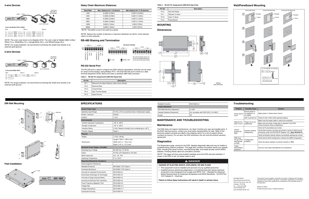
4-wire Devices

Daisy Chain Maximum Distances

Table 3: RS-232 Pin Assignments (DB9 EGX Signal Set)

Pin No.

Description

Wall/Panelboard Mounting

COM 1 COM 2

4-wire (use Belden 8723 or 9842)

EGX


Slave 1

Tx+


Rx+


Green


Tx-


White


Rx-


Rx+


Red


Tx+


Rx-


Black


Tx-


Terminator (MCT485 or MCTAS485)

Up to 32 devices

Slave 2

Green Rx+

White Rx-

RedTx+

BlackTx-

Baud Rate

Max. distance for 1–16 devices

Max distance for 17–32 devices

1200

10,000ft (3,048m)

10,000 ft (3,048m)


2400

10,000ft (3,048m)

5,000 ft (1,524m)


4800

10,000ft (3,048m)

5,000 ft (1,524m)


9600

10,000ft (3,048m)

4,000 ft (1,219m)


19200

5,000ft (1,524m)

2,500 ft (762m)


38400

5,000ft (1,524m)

1,500 ft (457m)

NOTE: This table is only to be used as a guide.

NOTE: Reduce the number of devices or maximum distances by half for 4-wire devices used in 2-wire networks.

Pin 6 Data Set Ready

Pin 7 Request To Send

Pin 8 Clear To Send

Pin 9 Ring Indicator

MOUNTING

Dimensions


Vertical Mounting

Vertical Flat Mounting

Horizontal Flat Mounting

1

Template

Template

Template


Panel

Panel

Panel


2

NOTE: The color code shown is for Beleden 8723. The color code for Belden 9842 is Blue/ White (Tx+), White/Blue (Tx-), Orange/White (Rx+), and White/Orange (Rx-).

NOTE: For surge protection, we recommend connecting the shield wire directly to an external earth ground.

2-wire Devices

Terminator (MCT-2W)


COM 1

COM 2


Up to 32 devices

2-wire (use Belden 9841)


EGX


Slave 1

Slave 2

Tx+

Blue

L+

Blue

L+

Tx-

White

L-

White

L-

Rx+


Rx-


NOTE: For surge protection, we recommend connecting the shield wire directly to an external earth ground.

RS-485 Biasing and Termination


COM 2


COM 1


Dip Switch Settings


ON


COM 2


4-wire


COM 1


COM 2


2-wire


COM 1


OFF


1

2

3


4


5

6

7

8

9 10


Txtermination


Rxtermination


– bias

+ bias


Txtermination


Rxtermination


– bias

+ bias


1

2

3


4


5

6


7

8

9 10


1

2

3


4


5

6

7

8

9 10


UP / ON


DOWN / OFF

4-wire and 2-wire daisy chains.


Dip switch settings shown are

the recommended settings for

RS-232 Serial Port

The RS-232 port is used to configure the EGX network parameters, and also can be used for serial communication using Modbus RTU. The EGX RS-232 port is wired as a data terminal equipment (DTE) device and uses a standard DB9 male connector.

Table 3: RS-232 Pin Assignments (DB9 EGX Signal Set)

Pin No.

Description

Pin 1

Received Line Signal Detector (Data Carrier Detect)


Pin 2

Received Data


Pin 3

Transmit Data


Pin 4

Data Terminal Ready


Pin 5

Signal Ground


0.407.88

(11)(221)

8.68

(221)

7.88 1.77

(201)(45)

3.05 (78)

0.401.07

(11)(28)

1.91

(49)

1.774.81

(45) (123)

1.44 (37)

1.070.59

(28) (15)


4.81


0.59

INCHES


(123)


(15)

(MILLIMETERS)


3

4

For all methods of mounting:

.036 in. (1 mm) min.

.046 in. (2 mm) max.

Pan head scres


6–32 (4 mm)

Panel

NOTE: Maximum drill size is #6 (two places)

DIN Rail Mounting


SPECIFICATIONS


Feet


Control Power Input


DIN Rail


Operating Input Range

24 Vdc (±10%) sourced by Class 2 rated power supply


Burden, maximum

8 Watts


Isolation

1.5 kV


Environmental


Ambient Operating Temperature

–30° to +80°C


Storage Temperature

–40° to +85°C


Humidity Rating

5–95% Relative Humidity (non-condensing) at +40°C


Pollution Degree

Class 2


Physical


Weight

1.5 lbs. (.68 kg)


Length (7.88 in. / 200.2 mm),


Dimensions

Width (4.81 in. / 122.2 mm),


Depth (1.07 in. / 27.2 mm)


Universal Power Supply (included)


Operating Input Voltage

90–264 Vac, 47–63 Hz


Output

24 Vdc (±2% Regulation), 20 watts


Safety Approvals

cUL, CE, TUV


Operating Temperature

0° to +40°C


Regulatory/Standards Compliance


Feet Installation


Electromagnetic Interference


Radiated Emissions

EN 55022 / FCC Class A


Feet


Conducted Emissions

EN 55022 / FCC Class A


Immunity for Industrial Environments

EN 61000-6-2


Electrostatic Discharge (Air Discharge)

EN 61000-4-2


Immunity to Surge (Impulse Wave)

EN 61000-4-5


Immunity to Electrical Fast Transients

EN 61000-4-4


Power Frequency Magnetic Field

EN 61000-4-8


Voltage Dips

EN 61000-4-11


Voltage Interruptions

EN 61000-4-11


Conducted Immunity

EN 61000-4-6


Radiated Immunity

EN 61000-4-3


Product Standards


USA (Miscellaneous Apparatus)

UL 508


Canada (Industrial Equipment)

cUL (complies with CSA C22.2, #14–M91)


Europe

CE


MAINTENANCE AND TROUBLESHOOTING

Maintenance

The EGX does not require maintenance, nor does it contain any user-serviceable parts. If the EGX requires service, contact your local sales representative for help. Refer to the technical support contacts provided in the shipping carton for a list of support phone numbers by country. Do not open the EGX enclosure; this will void the product warranty agreement.

Diagnostics

The Diagnostics page, served by the EGX, displays diagnostic data and may be helpful in troubleshooting network problems. This page also contains information about your specific EGX, including the serial number, manufacturing date, and media access control (MAC) address. Pressing Reset clears all cumulative counters.

NOTE: This page will show accumulated readings since the EGX was last activated. If power to the EGX is lost, all values reset to zero.

DANGER

HAZARD OF ELECTRIC SHOCK, EXPLOSION, OR ARC FLASH

This equipment must be installed and serviced only by qualified personnel.

Qualified persons performing diagnostics or troubleshooting that require electrical conductors to be energized must comply with NFPA 70 E – Standard for Electrical Safety Requirements for Employee Workplaces and OSHA Standards – 29 CFR Part 1910 Subpart S – Electrical.

Failure to follow these instructions will result in death or serious injury.

Troubleshooting

Problem

Possible Cause

Solution


Source power is


Power LED is

not applied or is

Apply power or check power source.

not lit.

not stable.


LED is burned out.

Check to see if other LEDs operate properly.


Ethernet link

Proper link is not

Make sure the proper cable is used and connected.


Make sure the proper media type is selected in the EGX

LED is not lit.

established.


Communications setup configuration.


Verify all IP parameters are correct.

Cannot


Incorrect network

Verify EGX receives requests (ping EGX by going to DOS prompt

browse the

configuration.

and typing “ping” and the EGX IP address, e.g., ping 199.0.62.41).

EGX.


Verify all browser internet options connections settings are correct.


SMS does


Verify that the EGX configuration matches the SMS configuration.

not go online

Configuration


with devices

problems

Verify the device address is entered correctly in SMS.

on EGX.


Forgot


administrator


Call your local sales representative for assistance.

password.


Schneider Electric

This product must be installed, connected, and used in compliance with prevailing

Power Monitoring and Control

standards and/or installation regulations. As standards, specifications, and designs

change from time to time, please ask for confirmation of the information given in

295 Tech Park Drive, Suite 100

this publication.

LaVergne, TN 37086


Tel: +1 (615) 287-3400

63230-314-200C2

www.powerlogic.com

© 2006 Schneider Electric. All Rights Reserved.

www.schneider-electric.com


Page 2
Image 2
Schneider Electric 63230-314-200C2 quick start Mounting, Specifications, Maintenance and Troubleshooting

63230-314-200C2 specifications

Schneider Electric is a global leader in energy management and automation, renowned for providing innovative solutions tailored to various industrial needs. Among its extensive portfolio, the Schneider Electric 63230-314-200C2 stands out, representing an exemplary product characterized by its versatility and advanced technology.

The Schneider Electric 63230-314-200C2 is primarily designed for monitoring and controlling electrical systems, making it essential for efficient energy management. One of its main features includes a robust communication interface that supports multiple protocols, enabling seamless integration with existing systems and enhancing interoperability. This functionality allows users to easily adopt smart technologies and optimize their energy consumption.

Another significant characteristic of the 63230-314-200C2 is its user-friendly interface. The device comes equipped with an intuitive display that offers real-time data visualization, ensuring that operators can monitor system performance at a glance. This feature reduces the complexity typically associated with industrial devices, allowing users to focus on critical decision-making processes without getting bogged down by technicalities.

The technology behind the 63230-314-200C2 showcases Schneider Electric's commitment to sustainability and efficiency. It utilizes advanced algorithms that facilitate energy data analysis, helping users identify trends and patterns that can lead to significant cost savings. By leveraging this information, companies can make informed choices about their energy usage, ultimately reducing their carbon footprint.

Safety is another paramount consideration, and the 63230-314-200C2 addresses this by incorporating various protective features. It is designed to withstand harsh industrial environments, ensuring reliable operation under challenging conditions. Furthermore, the product meets stringent international safety standards, providing users with peace of mind regarding its reliability and effectiveness.

In conclusion, the Schneider Electric 63230-314-200C2 embodies a blend of innovation, user-centric design, and sustainability. Its robust communication capabilities, intuitive interface, energy analysis technologies, and safety features make it an invaluable asset for any organization looking to optimize its electrical systems. As industries increasingly pivot towards smart energy solutions, the Schneider Electric 63230-314-200C2 positions itself as a forward-thinking choice that aligns with modern operational demands.