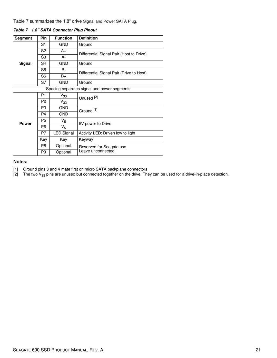
Table 7 summarizes the 1.8” drive Signal and Power SATA Plug.
Table 7 1.8” SATA Connector Plug Pinout
Segment | Pin | Function | Definition | |
| S1 | GND | Ground | |
|
|
|
| |
| S2 | A+ | Differential Signal Pair (Host to Drive) | |
|
|
| ||
| S3 | A- | ||
|
| |||
Signal |
|
|
| |
S4 | GND | Ground | ||
| S5 | B- | Differential Signal Pair (Drive to Host) | |
|
|
| ||
| S6 | B+ | ||
|
| |||
|
|
|
| |
| S7 | GND | Ground | |
|
|
|
| |
|
| Spacing separates signal and power segments | ||
|
|
|
| |
| P1 | V33 | Unused [2] | |
| P2 | V33 | ||
|
| |||
| P3 | GND | Ground [1] | |
|
|
| ||
| P4 | GND | ||
|
| |||
|
|
|
| |
Power | P5 | V5 | 5V power to Drive | |
P6 | V5 | |||
|
| |||
| P7 | LED Signal | Activity LED: Driven low to light | |
|
|
|
| |
| Key | Key | Keyway | |
|
|
|
| |
| P8 | Optional | Reserved for Seagate use. | |
| P9 | Optional | Leave unconnected. | |
|
|
|
| |
Notes:
[1]Ground pins 3 and 4 mate first on micro SATA backplane connectors
[2]The two V33 pins are unused but connected together on the drive. They can be used for a
SEAGATE 600 SSD PRODUCT MANUAL, REV. A | 21 |