8.0Installation
Barracuda ES.2 disk drive installation is a
SAS drives are designed to be used in a host system that provides a
Note. SAS drives are designed to be attached to the host system without I/O or power cables. If you intend the use the drive in a
Slide the carrier or tray into the appropriate bay in your host system using the instructions provided by the host system. This connects the drive directly to your system’s SAS connector. The SAS connector is normally located on a SAS backpanel. See Section 9.4.1 for additional information about these connectors.
Power is supplied through the SAS connector.
The drive is shipped from the factory
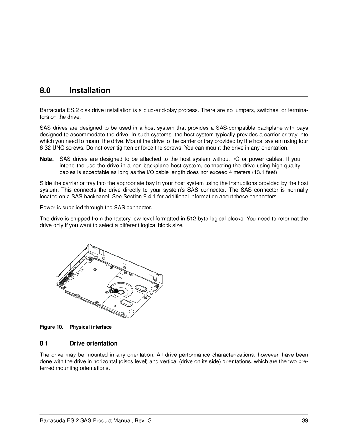
Figure 10. Physical interface
8.1Drive orientation
The drive may be mounted in any orientation. All drive performance characterizations, however, have been done with the drive in horizontal (discs level) and vertical (drive on its side) orientations, which are the two pre- ferred mounting orientations.
Barracuda ES.2 SAS Product Manual, Rev. G | 39 |