A combination of a
The TCTF is the mathematical statement of the transfer function through which the transmitter shall be capable of producing acceptable signals as defined by a receive mask. The transmission magnitude response of the TCTF in dB is given by the following equation for 1.5 Gbps:
S21
=
for 50 MHz < f < 1.5 GHz, and:
S21
= –5, 437dB
for 1.5 GHz < f < 5.0 GHz, where:
a) f is the signal frequency in hertz.
The transmission magnitude response of the TCTF in dB is given by the following equation for 3.0 Gbps:
S21 =
for 50 MHz < f < 3.0 GHz, and:
S21
= –10, 884dB
for 3.0 GHz < f < 5.0 GHz,
where f is the signal frequency in hertz.
The TCTF is used to specify the requirements on transmitters that may or may not incorporate
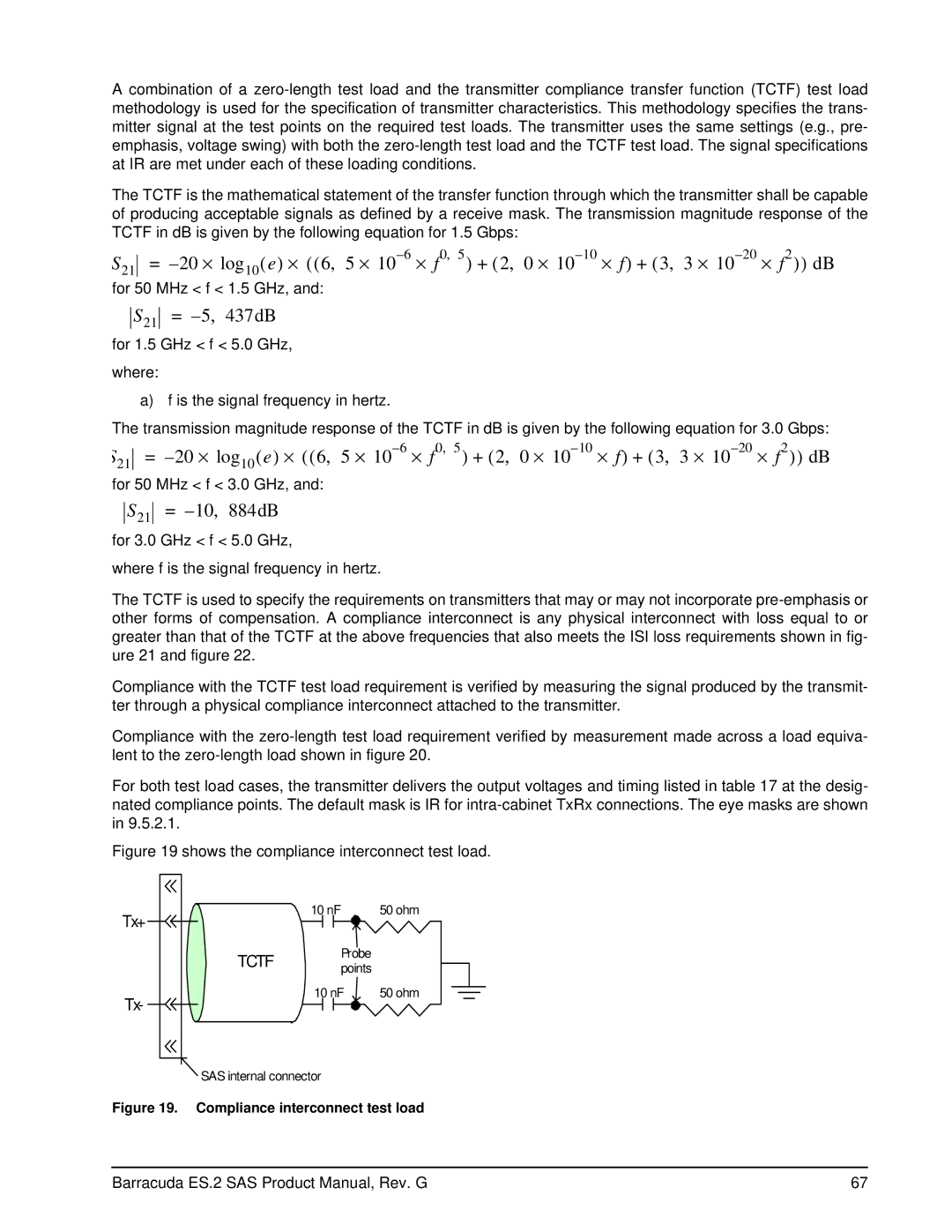
Compliance with the TCTF test load requirement is verified by measuring the signal produced by the transmit- ter through a physical compliance interconnect attached to the transmitter.
Compliance with the
For both test load cases, the transmitter delivers the output voltages and timing listed in table 17 at the desig- nated compliance points. The default mask is IR for
Figure 19 shows the compliance interconnect test load.
Tx+
TCTF
Tx-
10 nF | 50 ohm |
Probe |
|
points |
|
10 nF | 50 ohm |
SAS internal connector
Figure 19. Compliance interconnect test load
Barracuda ES.2 SAS Product Manual, Rev. G | 67 |
