Cheetah 73LP Product Manual, Rev. E | 21 |
6.0Physical/electrical specifications
This section provides information relating to the physical and electrical characteristics of the Cheetah 73LP drive.
6.1AC power requirements
None.
6.2DC power requirements
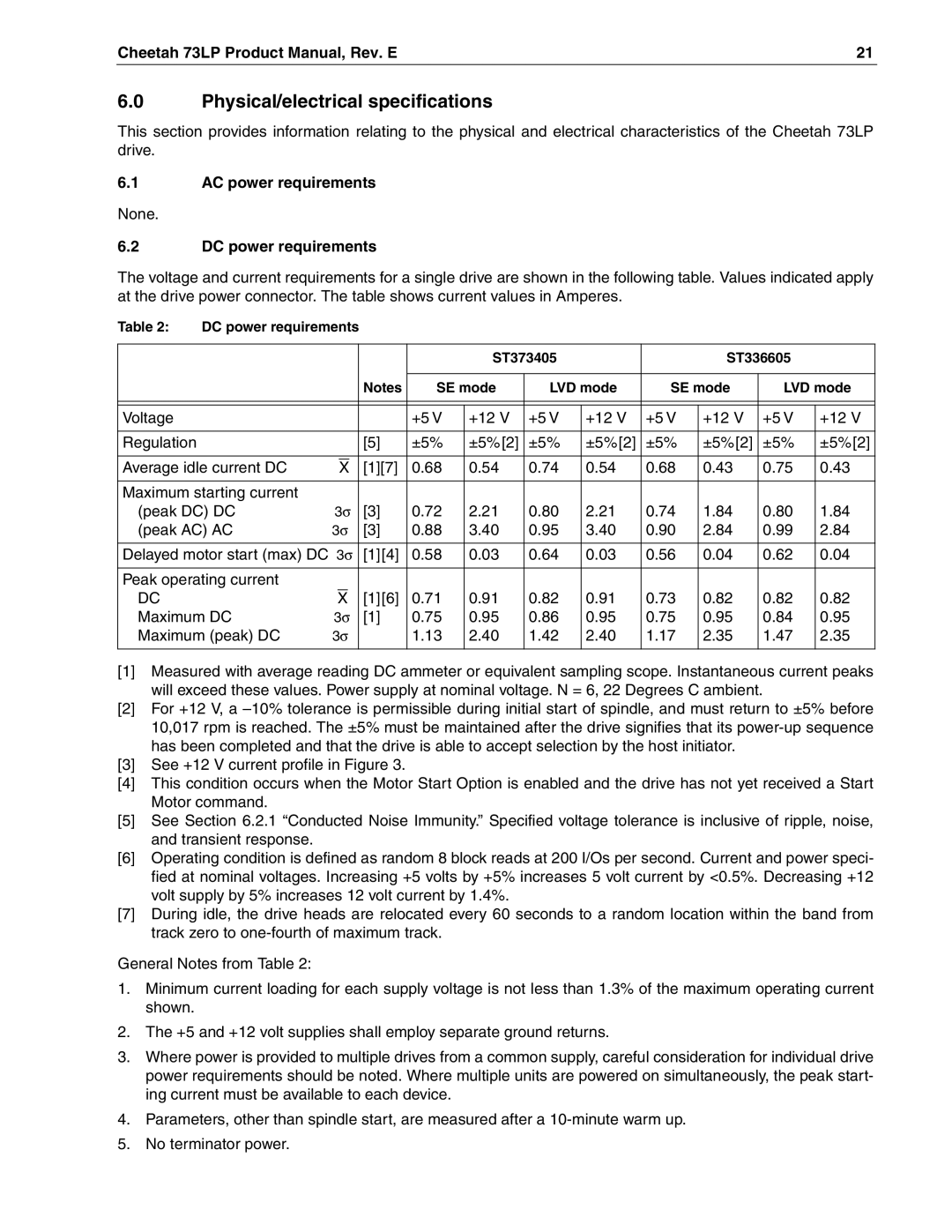
The voltage and current requirements for a single drive are shown in the following table. Values indicated apply at the drive power connector. The table shows current values in Amperes.
Table 2: | DC power requirements |
|
|
|
|
|
|
|
|
| ||||
|
|
|
|
|
|
|
|
|
|
|
|
|
|
|
|
|
|
|
|
|
|
| ST373405 |
|
| ST336605 |
| ||
|
|
|
|
|
|
|
|
|
|
|
|
|
| |
|
|
|
|
|
| Notes | SE mode | LVD mode | SE mode | LVD mode | ||||
|
|
|
|
|
|
|
|
|
|
|
|
|
|
|
|
|
|
|
|
|
|
|
|
|
|
|
|
|
|
Voltage |
|
|
|
|
|
| +5 V | +12 V | +5 V | +12 V | +5 V | +12 V | +5 V | +12 V |
|
|
|
|
|
|
|
|
|
|
|
|
|
|
|
Regulation |
|
|
|
|
| [5] | ±5% | ±5%[2] | ±5% | ±5%[2] | ±5% | ±5%[2] | ±5% | ±5%[2] |
|
|
|
|
|
|
|
|
|
|
|
|
|
| |
Average idle current DC |
|
|
|
| [1][7] | 0.68 | 0.54 | 0.74 | 0.54 | 0.68 | 0.43 | 0.75 | 0.43 | |
| X | |||||||||||||
|
|
|
|
|
|
|
|
|
|
|
|
|
| |
Maximum starting current |
|
|
|
|
|
|
|
|
|
|
|
|
| |
(peak DC) DC | 3σ | [3] | 0.72 | 2.21 | 0.80 | 2.21 | 0.74 | 1.84 | 0.80 | 1.84 | ||||
(peak AC) AC | 3σ | [3] | 0.88 | 3.40 | 0.95 | 3.40 | 0.90 | 2.84 | 0.99 | 2.84 | ||||
|
|
|
|
|
|
|
|
|
| |||||
Delayed motor start (max) DC 3σ | [1][4] | 0.58 | 0.03 | 0.64 | 0.03 | 0.56 | 0.04 | 0.62 | 0.04 | |||||
|
|
|
|
|
|
|
|
|
|
|
|
|
| |
Peak operating current |
|
|
|
|
|
|
|
|
|
|
|
|
| |
DC |
|
| X |
| [1][6] | 0.71 | 0.91 | 0.82 | 0.91 | 0.73 | 0.82 | 0.82 | 0.82 | |
Maximum DC | 3σ | [1] | 0.75 | 0.95 | 0.86 | 0.95 | 0.75 | 0.95 | 0.84 | 0.95 | ||||
Maximum (peak) DC | 3σ |
| 1.13 | 2.40 | 1.42 | 2.40 | 1.17 | 2.35 | 1.47 | 2.35 | ||||
|
|
|
|
|
|
|
|
|
|
|
|
|
|
|
[1]Measured with average reading DC ammeter or equivalent sampling scope. Instantaneous current peaks will exceed these values. Power supply at nominal voltage. N = 6, 22 Degrees C ambient.
[2]For +12 V, a
[3]See +12 V current profile in Figure 3.
[4]This condition occurs when the Motor Start Option is enabled and the drive has not yet received a Start Motor command.
[5]See Section 6.2.1 “Conducted Noise Immunity.” Specified voltage tolerance is inclusive of ripple, noise, and transient response.
[6]Operating condition is defined as random 8 block reads at 200 I/Os per second. Current and power speci- fied at nominal voltages. Increasing +5 volts by +5% increases 5 volt current by <0.5%. Decreasing +12 volt supply by 5% increases 12 volt current by 1.4%.
[7]During idle, the drive heads are relocated every 60 seconds to a random location within the band from track zero to
General Notes from Table 2:
1.Minimum current loading for each supply voltage is not less than 1.3% of the maximum operating current shown.
2.The +5 and +12 volt supplies shall employ separate ground returns.
3.Where power is provided to multiple drives from a common supply, careful consideration for individual drive power requirements should be noted. Where multiple units are powered on simultaneously, the peak start- ing current must be available to each device.
4.Parameters, other than spindle start, are measured after a
5.No terminator power.