ST373405LW/LWV/LC/LCV ST336605LW/LC/LCV
Page
ST373405LW/LWV/LC/LCV ST336605LW/LC/LCV
Page
Revision Date Writer/Engineer Sheets Affected
Revision status summary sheet
Page
Contents
Interface requirements
Defect and error management
Installation
Seagate Technology support services
Cheetah 73LP Product Manual, Rev. E Vii
List of Figures
Page
Cheetah 73LP family drive ST373405LW shown
Scope
Cheetah 73LP Product Manual, Rev. E
Applicable standards and reference documentation
Taiwanese Bsmi
Australian C-Tick
Korean MIC
General description
Cheetah 73LP family drive
Reliability
Cheetah 73LP Product Manual, Rev. E Standard features
Media characteristics
Performance
Unformatted and formatted capacities
Factory installed accessories
Options factory installed
Accessories user installed
Performance characteristics
Prefetch/multi-segmented cache control
Ultra2 Scsi Ultra3 Scsi
Start/stop time
Caching write data
Cheetah 73LP Product Manual, Rev. E Cache operation
Prefetch operation
Reliability specifications
Service philosophy
Reliability and service
Preventive maintenance
Service life
Controlling S.M.A.R.T
7 S.M.A.R.T
Determining rate
Performance impact
Milliseconds
Reporting control
Invoking DST
State of the drive prior to testing
DST Failure Definition
Implementation
Log page entries
Short and extended tests
Short test Function Code 001b
Extended test Function Code 010b
Product repair and return information
Cheetah 73LP Product Manual, Rev. E Product warranty
Shipping
Cheetah 73LP Product Manual, Rev. E
DC power requirements
Physical/electrical specifications
AC power requirements
3 12 V Current profile
Power sequencing
Conducted noise immunity
Typical ST336605 drive +12 V current profile
Typical ST336605 drive +5 V current profile
Amperes
000 900 800 700 600
Effective altitude sea level
Temperature
Cheetah 73LP Product Manual, Rev. E Environmental limits
Relative humidity
Shock
Shock and vibration
Recommended mounting
Acoustics
Air cleanliness
Vibration
LW and LWV mounting configuration dimensions
LC and LCV mounting configuration dimensions
Drive internal defects
Defect and error management
Drive error recovery procedures
Scsi systems errors
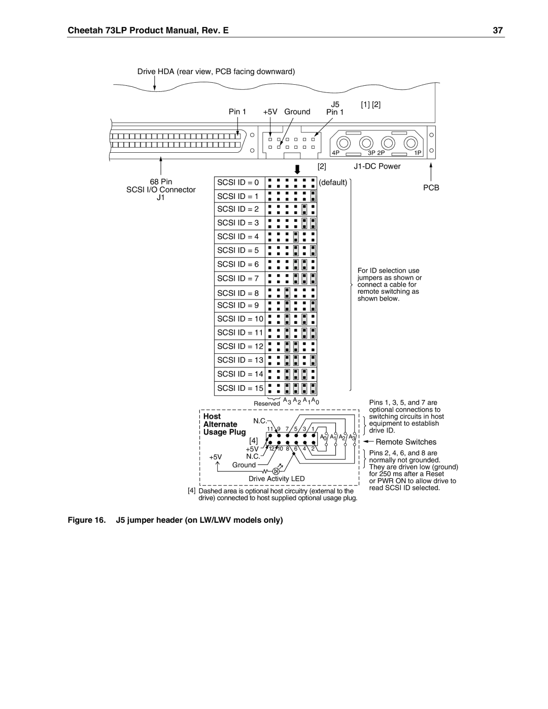
Drive ID/option select header
Installation
Configure drive options
Formatting
Do not install jumpers retain cover
J5 jumper header on LW/LWV models only
J2 option select header
Does not apply to LC/LCV model
Cheetah 73LP Product Manual, Rev. E Function description
Cooling
Drive orientation
Grounding
Cheetah 73LP Product Manual, Rev. E Drive mounting
Cheetah 73LP Product Manual, Rev. E
Scsi interface messages supported
Interface requirements
Scsi interface commands supported
Cheetah 73LP Product Manual, Rev. E
Cheetah 73LP Product Manual, Rev. E
Inquiry Vital Product data
Mode Sense data
DEF CHG
Cheetah 73LP Product Manual, Rev. E
Condition/feature supported by
Physical interface
DC cable and connector
2 REQ/ACK offset
Pin Power
Scsi interface cable requirements
Scsi interface physical description
ST373405LC/LCV and ST336605LC/LCV
Mating connectors
Mating connectors for LW and LWV model drives
Mating connectors for LC and LCV model drives
Cheetah 73LP Product Manual, Rev. E
Scsi ID
Right-angle to Pcba connectors
650±.005 155 100 346
Front View
GND
+DBP1
62Cheetah 73LP Product Manual, Rev. E
REQ +REQ
Multimode-SE and LVD alternatives
LVD output characteristics
Electrical description
Single-ended drivers/receivers
General cable characteristics
Terminator requirements
Cables for low voltage differential drivers/receivers
LC and LCV drives
Disc drive Scsi timing
Drive activity LED
Spindle status Command status LED status
Cheetah 73LP Product Manual, Rev. E
Technical Support
Seagate Technology support services Online Services
Automated Services
Presales Support
European Support Services
Customer Service CSO
USA/Canada/Latin America Support Services
Call Center Toll-free Direct dial
Africa/Middle East Support Services
Asia/Pacific Support Services
Cheetah 73LP Product Manual, Rev. E
Index
Cheetah 73LP Product Manual, Rev. E
Cheetah 73LP Product Manual, Rev. E
Scam Scsi
Scsi ID
80Cheetah 73LP Product Manual, Rev. E

 Remote Switches