32 | Elite 23 Installation Guide, Rev. A | ||
|
|
|
|
[3]
K
H![]()
![]() G
G
D ![]()
A
E
[2]
C
B
J
[4]
L
F
[1]
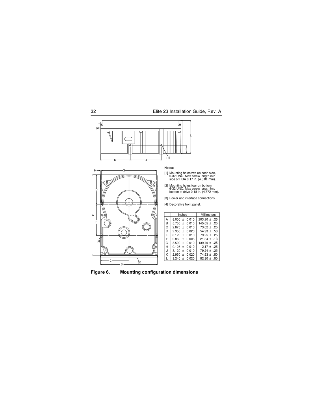
Notes:
[1]Mounting holes two on each side,
[2]Mounting holes four on bottom,
[3]Power and interface connections.
[4]Decorative front panel.
| Inches | Millimeters | ||||
A | 8.000 | ± | 0.010 | 203.20 | ± | .25 |
B | 5.750 | ± | 0.010 | 145.05 | ± | .25 |
C | 2.875 | ± | 0.010 | 73.02 | ± | .25 |
D | 2.950 | ± | 0.020 | 54.93 | ± | .50 |
E | 3.120 | ± | 0.010 | 79.25 | ± | .25 |
F | 0.860 | ± | 0.005 | 21.84 | ± | .13 |
G | 5.500 | ± | 0.010 | 139.70 | ± | .25 |
H | 0.125 | ± | 0.010 | 2.17 | ± | .25 |
J | 3.120 | ± | 0.010 | 79.24 | ± | .25 |
K | 2.950 | ± | 0.020 | 74.93 | ± | .50 |
L | 3.240 | ± | 0.020 | 82.30 | ± | .50 |