4.0ATA interface
These drives use the
For detailed information about the ATA interface, refer to the draft of AT Attachment with Packet Interface Extension
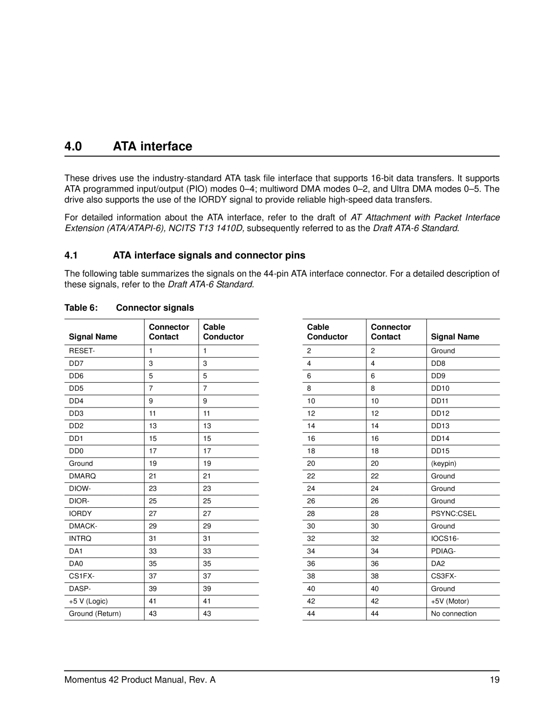
4.1ATA interface signals and connector pins
The following table summarizes the signals on the
Table 6: | Connector signals |
| |
|
|
|
|
|
| Connector | Cable |
Signal Name | Contact | Conductor | |
|
|
|
|
RESET- |
| 1 | 1 |
|
|
|
|
DD7 |
| 3 | 3 |
|
|
|
|
DD6 |
| 5 | 5 |
|
|
|
|
DD5 |
| 7 | 7 |
|
|
|
|
DD4 |
| 9 | 9 |
|
|
|
|
DD3 |
| 11 | 11 |
|
|
|
|
DD2 |
| 13 | 13 |
|
|
|
|
DD1 |
| 15 | 15 |
|
|
|
|
DD0 |
| 17 | 17 |
|
|
|
|
Ground |
| 19 | 19 |
|
|
|
|
DMARQ |
| 21 | 21 |
|
|
|
|
DIOW- |
| 23 | 23 |
|
|
|
|
DIOR- |
| 25 | 25 |
|
|
|
|
IORDY |
| 27 | 27 |
|
|
|
|
DMACK- |
| 29 | 29 |
|
|
|
|
INTRQ |
| 31 | 31 |
|
|
|
|
DA1 |
| 33 | 33 |
|
|
|
|
DA0 |
| 35 | 35 |
|
|
|
|
CS1FX- |
| 37 | 37 |
|
|
|
|
DASP- |
| 39 | 39 |
|
|
|
|
+5 V (Logic) |
| 41 | 41 |
|
|
| |
Ground (Return) | 43 | 43 | |
|
|
|
|
Cable | Connector |
|
Conductor | Contact | Signal Name |
|
|
|
2 | 2 | Ground |
|
|
|
4 | 4 | DD8 |
|
|
|
6 | 6 | DD9 |
|
|
|
8 | 8 | DD10 |
|
|
|
10 | 10 | DD11 |
|
|
|
12 | 12 | DD12 |
|
|
|
14 | 14 | DD13 |
|
|
|
16 | 16 | DD14 |
|
|
|
18 | 18 | DD15 |
|
|
|
20 | 20 | (keypin) |
|
|
|
22 | 22 | Ground |
|
|
|
24 | 24 | Ground |
|
|
|
26 | 26 | Ground |
|
|
|
28 | 28 | PSYNC:CSEL |
|
|
|
30 | 30 | Ground |
|
|
|
32 | 32 | IOCS16- |
|
|
|
34 | 34 | PDIAG- |
|
|
|
36 | 36 | DA2 |
|
|
|
38 | 38 | CS3FX- |
|
|
|
40 | 40 | Ground |
|
|
|
42 | 42 | +5V (Motor) |
|
|
|
44 | 44 | No connection |
|
|
|
Momentus 42 Product Manual, Rev. A | 19 |