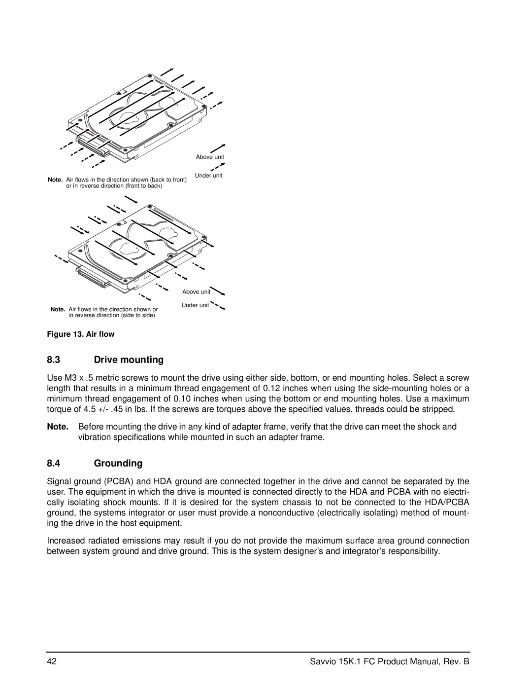
Note. Air flows in the direction shown (back to front) or in reverse direction (front to back)
Above unit
Under unit
Note. Air flows in the direction shown or in reverse direction (side to side)
Figure 13. Air flow
Above unit![]()
Under unit
8.3Drive mounting
Use M3 x .5 metric screws to mount the drive using either side, bottom, or end mounting holes. Select a screw length that results in a minimum thread engagement of 0.12 inches when using the
Note. Before mounting the drive in any kind of adapter frame, verify that the drive can meet the shock and vibration specifications while mounted in such an adapter frame.
8.4Grounding
Signal ground (PCBA) and HDA ground are connected together in the drive and cannot be separated by the user. The equipment in which the drive is mounted is connected directly to the HDA and PCBA with no electri- cally isolating shock mounts. If it is desired for the system chassis to not be connected to the HDA/PCBA ground, the systems integrator or user must provide a nonconductive (electrically isolating) method of mount- ing the drive in the host equipment.
Increased radiated emissions may result if you do not provide the maximum surface area ground connection between system ground and drive ground. This is the system designer’s and integrator’s responsibility.
42 | Savvio 15K.1 FC Product Manual, Rev. B |