getting to know your band saw
Frame
Tension
Catch
10
Switch
7 Sawdust Hose Clip
Ejection
Port
NOTE: Cover shown open for clarity
Cover
9 Wrench Holder
2 Upper Slide
Lock Knob
. Table
Tracking Adjustment
Set Screw
5 Tension
Lock Knob
8 Cover Hinges
1Blade
Guides
4Beve
Scale Bevel indicator
3Table Lock Knob
..................................................=r,H,,=l= | =ll,i H= | = | ii | H | =H== | ,i = | ill= | ,i,i | =f,l= |
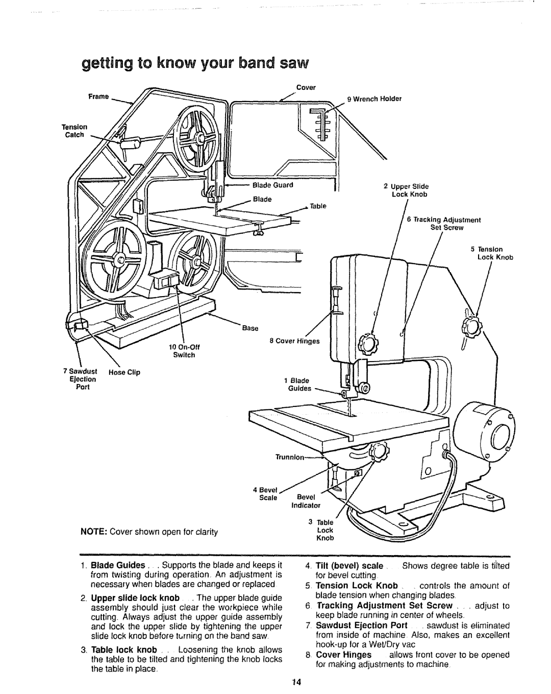
1,. Blade Guides.. Supports the blade and keeps it from twisting during operation, An adjustment is necessary when blades are changed or replaced
2.Upper slide lock knob , The upper'blade guide assembly should just clear the workpiece while cutting Always adjust the upper guide assembly and lock the upper slide by tightening the upper slide lock knob before turning on the band saw,
3 Table lock knob , , Loosening the knob allows the table to be tilted and tightening the knob locks the table in place.
4, Tilt (bevel) scale • Shows degree table is t/Ited
for bevel cutting
5 Tension Lock Knob • • controls the amount of blade tension when changing blades
6 Tracking Adjustment Set Screw _ ,, adjust to keep blade running in center of wheels,
7 Sawdust Ejection Port , sawdust is eliminated from inside of machine Also. makes an exceJlent
8 Cover Hinges allows front cover to be opened for making adjustments to machine
14