OPERATION cont.

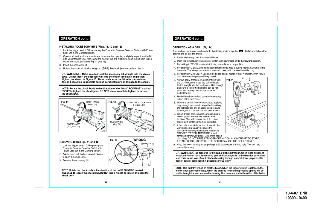
INSTALLING ACCESSORY BITS (Figs. 11, 12 and 13)

1.Lock the trigger switch Off by placing the Forward / Reverse Selector Switch with Power Lock-Off in the Center position.

2.Open or close the chuck jaws to a point where the opening is slightly larger than the bit size you intend to use. Also, raise the front of the drill slightly to keep the bit from falling out of the chuck jaws (see Fig. 11 and 12).

3.Insert the accessory bit.

4.Rotate the chuck clockwise to tighten (GRIP) the chuck jaws securely on the bit.

!WARNING: Make sure to insert the accessory bit straight into the chuck jaws. Do not insert the accessory bit into the chuck jaws at an angle then tighten, as shown in Figure 13. This could cause the bit to be thrown from the drill, resulting in possible serious personal injury or damage to the chuck.

NOTE: Rotate the chuck body in the direction of the “HAND POINTING” marked “GRIP” to tighten the chuck jaws. DO NOT use a wrench to tighten or loosen the chuck jaws.

OPERATION cont.

OPERATION AS A DRILL (Fig. 14)

Turn and set the torque clutch collar to the drilling position symbol . Install and tighten the desired drill bit into the chuck.

1.Install the battery pack into the drill/driver.

2.Push the forward/reverse selector switch with power lock-off to the forward position.

3.For drilling in WOOD, use twist drill bits, spade bits and auger bits.

4.For drilling in METAL, use high speed twist drill bits. Use a cutting lubricant when drilling in metals. The exceptions are cast iron and brass, which should be drilled dry.

5.For drilling in MASONRY, use carbide tipped bits or masonry bits. A smooth, even flow of dust indicates the proper drilling speed.

6. Always apply pressure in a straight line with

Fig. 14

the bit. If necessary, use the bubble levels


to drill straight into the workpiece. Use enough


pressure to keep the bit biting, but do not


push hard enough to stall the motor or

Companion

deflect the bit.

7. Hold drill /driver firmly to control the twisting action of the drill/ driver.

Fig. 11

CLOSE JAWS (to tighten bit)

OPEN JAWS (insert bit)

9

7 5

3

1

Fig. 12

COUNTER-CLOCKWISE


(Release Bit)


9


7


5


CLOCKWISE

3

Co


(Grip Bit)


pani


1

m

on


8. Move the drill bit into the workpiece, applying only enough pressure to keep the bit cutting. Do not force the drill or apply side pressure to elongate a hole. Let the tool do the work.

9. When drilling hard, smooth surfaces, use a center punch to mark the desired hole location. This will prevent the drill bit from slipping off-center as the hole is started.

10. If the drill/driver stalls, or the bit jams in the workpiece, it is usually because the

drill /driver is being overloaded. RELEASE TRIGGER SWITCH IMMEDIATELY and remove bit from workpiece. Determine cause

REMOVING BITS (Figs. 11 and 12)

1.Lock the trigger switch Off by placing the Forward / Reverse Selector Switch with Power Lock-Off in the Center position.

2.Rotate the chuck body counterclockwise to open the chuck jaws.

3.Remove the accessory bit.

Fig. 13

WRONG


9


7


5


anion


Comp


3


1

of stalling. DO NOT PRESS TRIGGER OFF AND ON IN AN ATTEMPT TO START A STALLED DRILL /DRIVER – THIS COULD DAMAGE THE DRILL /DRIVER.

11.Keep the motor running when pulling the bit back out of a drillled hole. This will help prevent jamming.

!WARNING:Be prepared for binding at bit breakthrough. When these situations occur, drill/driver has a tendency to grab and kick opposite to the direction of rotation and could cause loss of control when breaking through material. If not prepared, this loss of control could result in possible serious injury.

NOTE: Rotate the chuck body in the direction of the HAND POINTING marked RELEASE to loosen the chuck jaws. DO NOT use a wrench to tighten or loosen the chuck jaws.

20

NOTE: This drill/driver has an electric brake. When the trigger switch is released, the chuck stops turning instantly. When the brake is functioning properly, sparks will be visible through the vent slots on the housing. This is normal and is the action of the brake.

21

10-4-07 Drill

10300-10400

Page 11
Image 11
Sears 172.104, 172.103 Installing Accessory Bits Figs , 12, Operation AS a Drill Fig, Removing Bits Figs

172.104, 172.103 specifications

The Sears 172.103 and 172.104 are two notable models in the Sears line of home appliances, specifically designed to meet the needs of modern households while delivering reliability and efficiency. Both models are renowned for their robust construction, user-friendly interfaces, and a range of features that cater to the demands of everyday living.

One of the standout characteristics of the Sears 172.103 and 172.104 is their energy efficiency. These models comply with strict energy conservation standards, making them eco-friendly options for consumers looking to reduce their carbon footprint and energy bills. Both units are equipped with advanced energy management systems that intelligently monitor and adjust their power consumption based on usage patterns.

In terms of technology, the Sears 172.103 and 172.104 integrate smart capabilities that allow for remote monitoring and control. Using a dedicated mobile app, users can adjust settings, receive notifications, and troubleshoot issues from anywhere, which adds a layer of convenience for busy households. This technology not only enhances user experience but also ensures that appliances operate at optimal levels, thus prolonging their lifespan.

The design of these models reflects a sleek and modern aesthetic, with intuitive controls that make operation straightforward for users of all ages. The ergonomic layout of buttons and digital displays ensures that users can easily navigate through various settings and options, reducing the learning curve typically associated with new appliances.

Both models come with a variety of features aimed at enhancing functionality. For instance, they offer customizable settings that can cater to specific cooking or cleaning preferences. This personalization aspect is a great benefit for families looking to streamline their routines while maximizing efficiency.

Durability is another key feature of the Sears 172.103 and 172.104. Constructed with high-quality materials, they are built to withstand daily wear and tear. This durability, combined with relatively low maintenance requirements, makes these models a cost-effective choice over the long term.

In summary, the Sears 172.103 and 172.104 models exemplify the ideal balance of modern technology, energy efficiency, user-friendliness, and durability. These appliances not only meet the practical needs of consumers but also incorporate advanced features that make them standout options in the competitive home appliance market. Their combination of efficiency and reliability positions them as solid investments for households looking to upgrade their home technology.