ASSEMBLY
ASSEMBLY OF RECOVERY TANK
AND SOLUTION TANK
See Figure 2
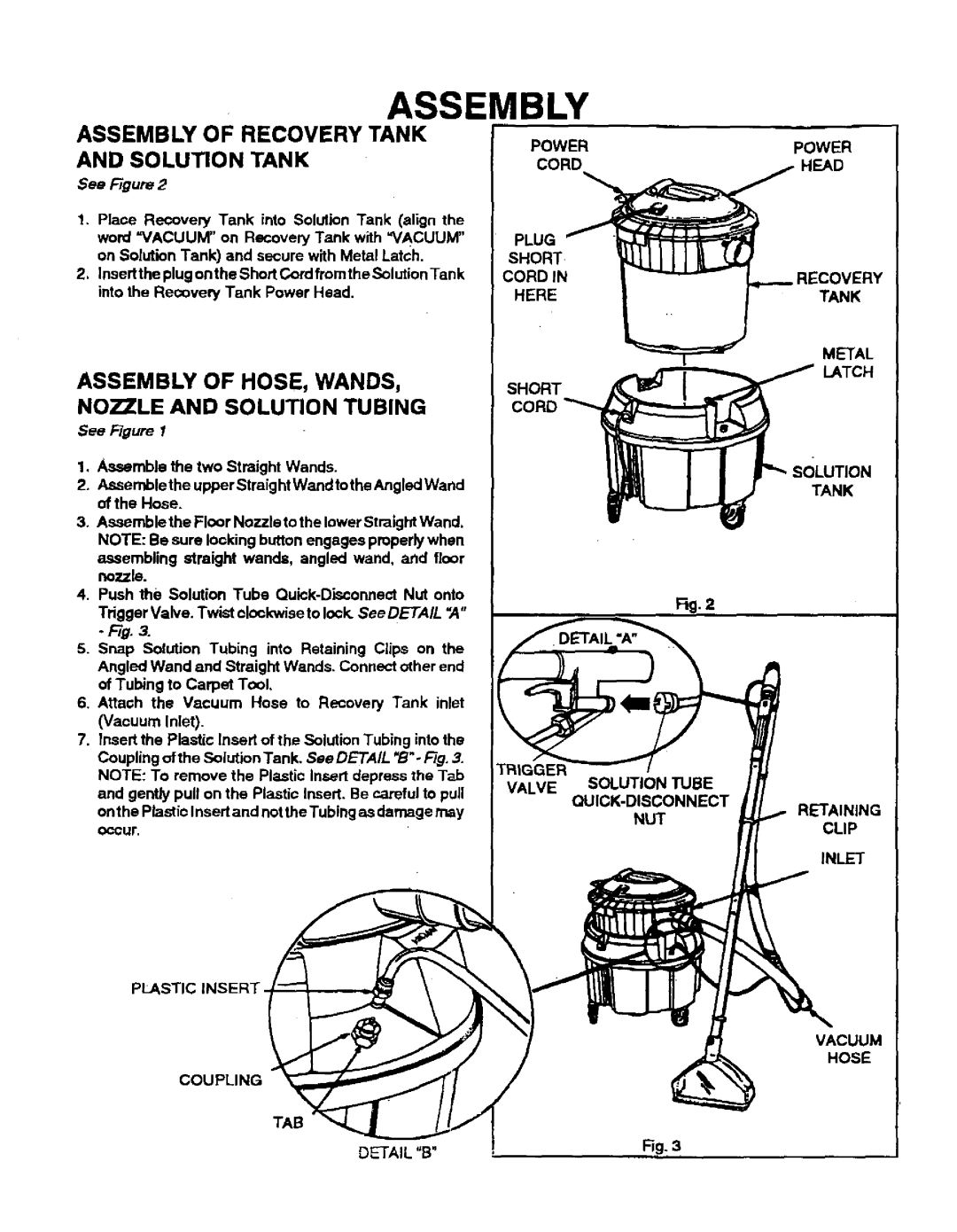
1. Place Recovery Tank into Solution Tank (align the word "VACUUM" on Recovery Tank with =VACUUM" on Solution Tank) and secure with Metal Latch.
2, Insert the plug onthe Short Cord from the Solution Tank into the Recovery Tank Power Head.
ASSEMBLY OF HOSE, WANDS,
NOZZLE AND SOLUTION TUBING
See Figure I
1.Assemble the two Straight Wands.
2.Assemblethe upper Straight Wand tothe Angled Wand of the Hose.
3.Assemble the Floor Nozzle to the lower Straight Wand, NOTE: Be sure locking button engages properly when
assembling straight wands, angled wand, and floor nozzle.
4, Push the Solution Tube
Tdgger Valve. Twist clockwise to lock. See DETAIL ",4"
5.Snap Solution Tubing into Retaining Clips on the Angled Wand and Straight Wands. Connect other end of Tubing to Carpet Tool,
6.Attach the Vacuum Hose to Recovery Tank inlet (Vacuum Inlet).
7.Insert the Plastic Insert of the Solution Tubing into the Coupling of the Solution Tank. See DETAIL "B"o Fig. 3.
NOTE: To remove the Plastic Insert depress the Tab and gently pull on the Plastic Insert. Be careful to pull
on the Plastic Insert and not the Tubing as damage may
occur.
PLASTIC INSERT
COUPLING
TAB
DETAIL "B"
| POWER |
| EAD |
PLUG |
|
SHORT |
|
CORDIN | RECOVERY |
HERE | TANK |
| METAL |
| LATCH |
SHORT |
|
CORD |
|
| TANK |
| Fig. 2 |
RETAINING
CLIP
INLET
VACUUM
HOSE
Fig, 3