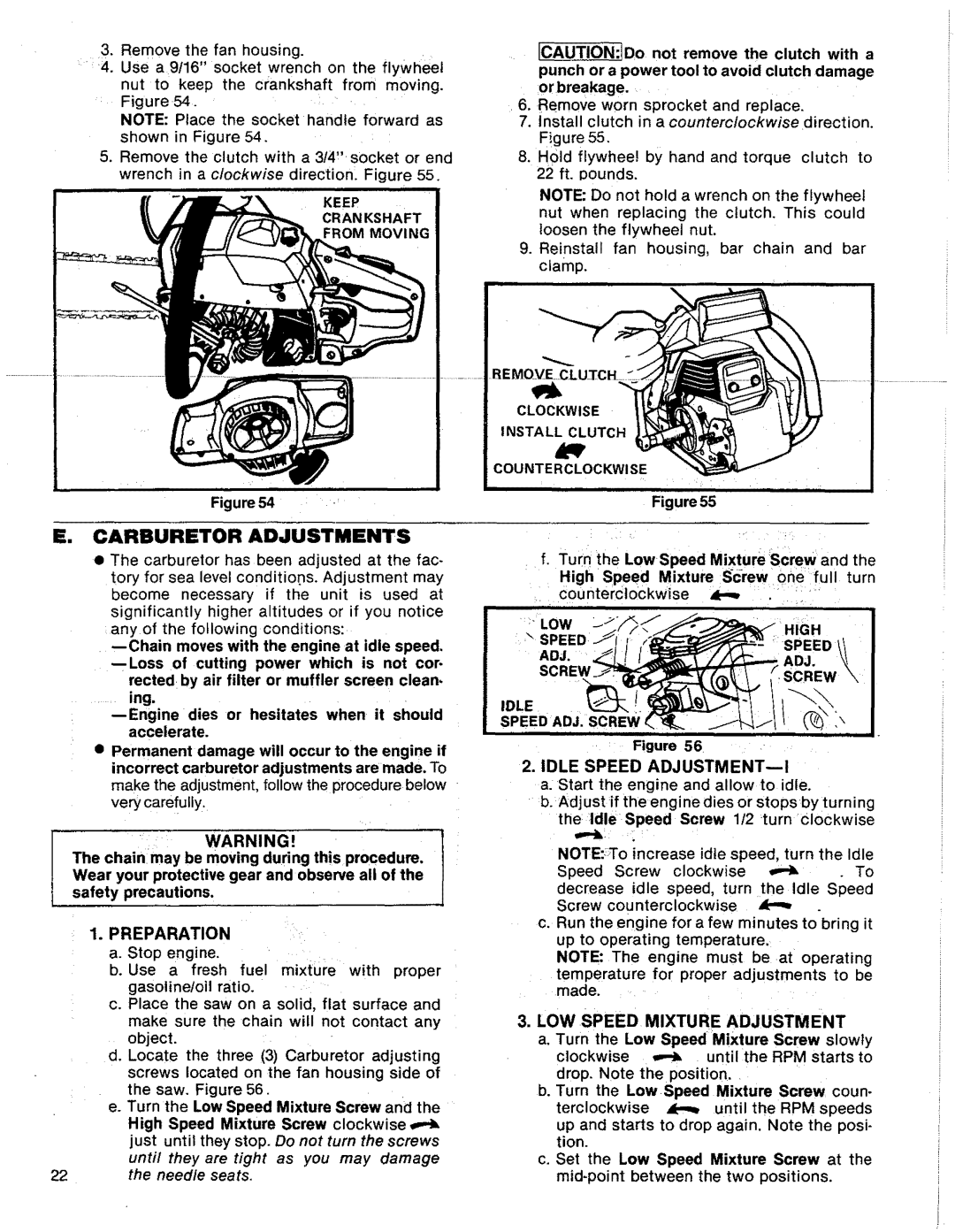
3. Remove the fan housing. | _ |
4.Use a 9!16" socket wrench on the flywheel nut to keep the crankshaft from moving.
Figure54.'
NOTE: Place the socket handle forward as shown in Figure 54.
5.Remove the clutch with a 314,. socket or end wrench in a clockwise direction:. Figure 55.
KEEP
CRANKSHAFT
FROM MOVING
Figure 54
E. CARBURETOR ADJUSTMENTS
•The carburetor has been adjusted at the fac- tory for sea level conditions. Adjustment may become necessary if the unit is used at significantly higher altitudes or if you notice anyof the following conditions:
rected by air filter or muffler screen clean-
.... ing.
•Permanent damage will occur to the engine if incorrect carburetor adjustments are made. To make the adjustment, follow the procedure below very carefully.
|
| WARNING! |
| l |
The chainmay be moving during this procedure. | ] | |||
Wear your protective gear and observe all of the | ||||
safety | precautions. |
| ||
1. PREPARATION | :" |
| ||
a. | Stop engine. |
|
| |
b. Use a fresh fuel mixture with proper |
| |||
| gasolineloil | ratio. |
|
|
C, | Place the | saw on a | solid, flat surface and |
|
make sure the chain will not contact any object.
d. Locate the three (3) Carburetor adjusting screws located on the fan housing side of the saw. Figure 56.
e.Turn the Low Speed Mixture Screw and the
High Speed Mixture Screw clockwise
just until they stop. Do not turn the screws
until they are tight as you may damage
22the needle seats.
[CAUTION:IDo not remove the clutch with a
punch or a power tool to avoid clutch damage orbreakage.
6, Remove worn sprocket and replace.
7.install clutch in a counterc/ockwise direction.
Figure 55,
8.Hold flywhee! bY hand and torque clutch to 22 ft. pounds.
NOTE: Do not hold a wrench on the flywheel nut when replacing the clutch, This could loosen the flywheel nut.
9.Reinstall fan housing, bar chain and bar clamp.
\
CLOCKWISE
INSTALL CLUTCH
COUNTERCLOCKWI SE
Figure 55
i ii':
f. Turn the LowSpeed Mixture Screw and the
HighSpeed | Mixture | |||||
. €ounterClockwise | _ | : | i | ..... i |
| |
' m |
|
| i | i | i | ,, |
_:_" |
|
|
| HIGH |
| |
\ |
|
|
| _:SPEED ! |
| |
ADJ. |
|
|
| ADJ. |
| |
SCRE_ |
|
|
|
|
|
|
IDLE |
|
|
| 1 |
|
|
SPEED ADJ. SCREW t |
|
|
|
|
| |
II Ir | i iii |
|
| I | i ii | ml i |
.... | Figure 56 |
|
| , |
|
|
2.IDLE SPEED ADJUSTMENT--!
a. Start the engine and allow to idle.
•b. Adjust ff the engine dies or stopsby itu rning the Idle Speed Screw 1/2 _turnclockwise
NOTE::To increase idle speed, turn the Idle
Speed Screw clockwise _To
decrease idle speed, turn the Idle Speed
Screw counterclockwise
c. Run the engine for a few minutes to bring it up to operating temperature.
NOTE: The engine must beat operating
temperature for proper adjustments to be made.
3.LOW SPEED MIXTURE ADJUSTMENT
a. Turn the Low Speed Mixture Screw slowty
clockwise _ until the RPM starts to
drop. Note the position.
b. Turn the LowSpeed Mixture Screw coun-
terclockwise _ until the RPM speeds
up and starts to drop again. Note the posi- tion.
c. Set the Low Speed Mixture Screw at the mid*point between the two positions.